Starting a winter bike, or should we call it an "All Roads?" Winter bike sounds better to me - less pretentious.
The BB only has sockets for the chainstays, sort of a mongrel design, but nice because its insensitive to angles between DT, ST and chainstays.
Filing malleable metals is sort of fun. Everything doesn't come off as chips.
This may look like a 3D picture where you're seeing the outside of the near wall and the inside of the far wall, but mostly you're just seeing the near wall.
Filing has pushed the edge back, leaving a thin layer of metal still connected to the tube.
Here the deburring tool has started to carve that edge off.
Carving the down tube has a similar ledge.
A lugged BB is used to scribe a like for the cope. Because this represents the inside of the shell, its actually too tight of a curve.
You can see the gap here. A sanding drum helps make the adjustment quickly.
Soon it looks like this - tight and tidy.
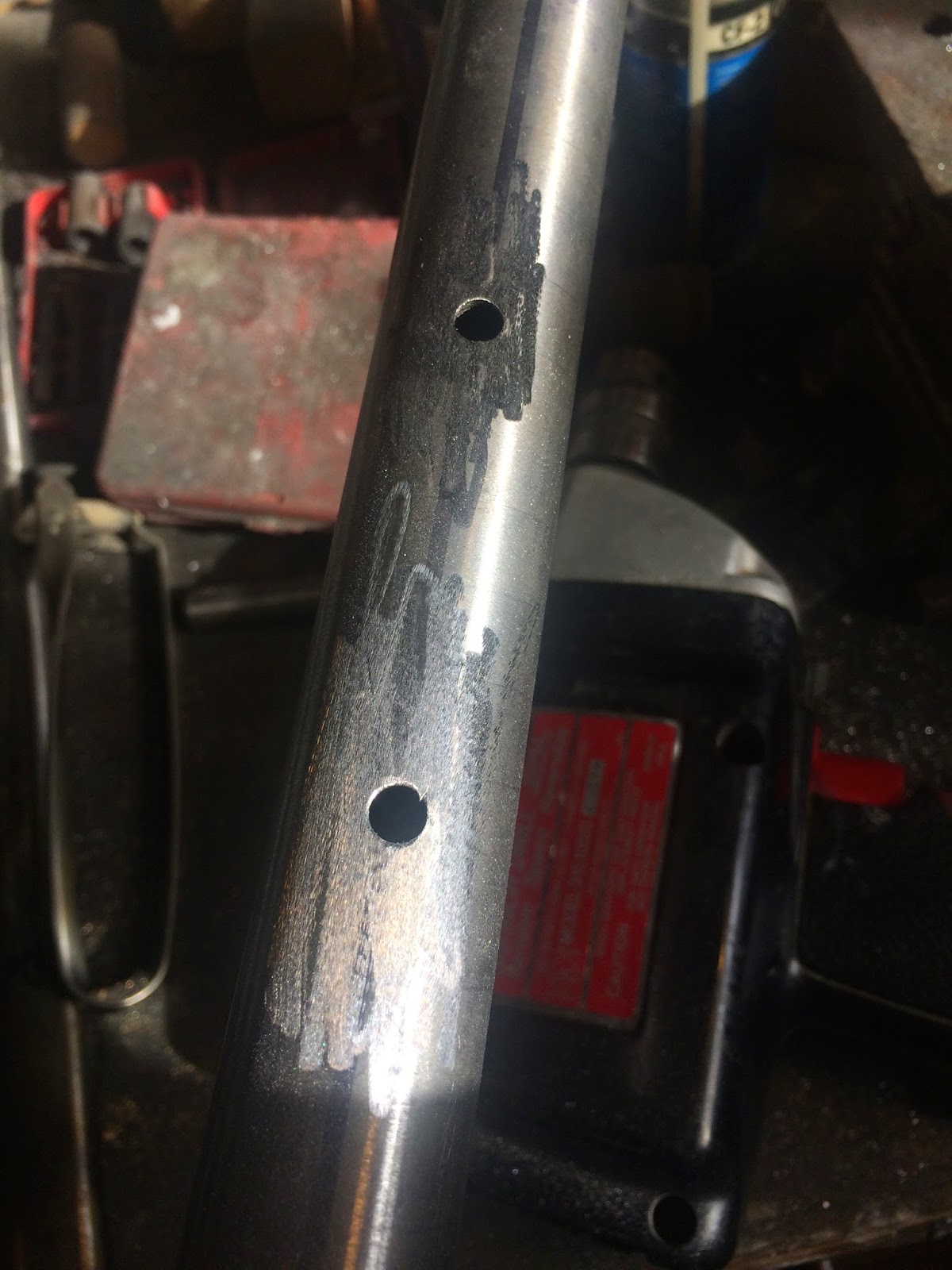
The seat tube, BTW, is old Columbus SLX. SLX used spiral reinforceing ribs at the butts to add strength with minimal weight. This is commonly called rifling.
I don't recall having ever seen a clear pictures of this. The Internet now has at least one clear picture now of SLX rifling. Note, as the seat tube, this only has the rifling at the bottom.
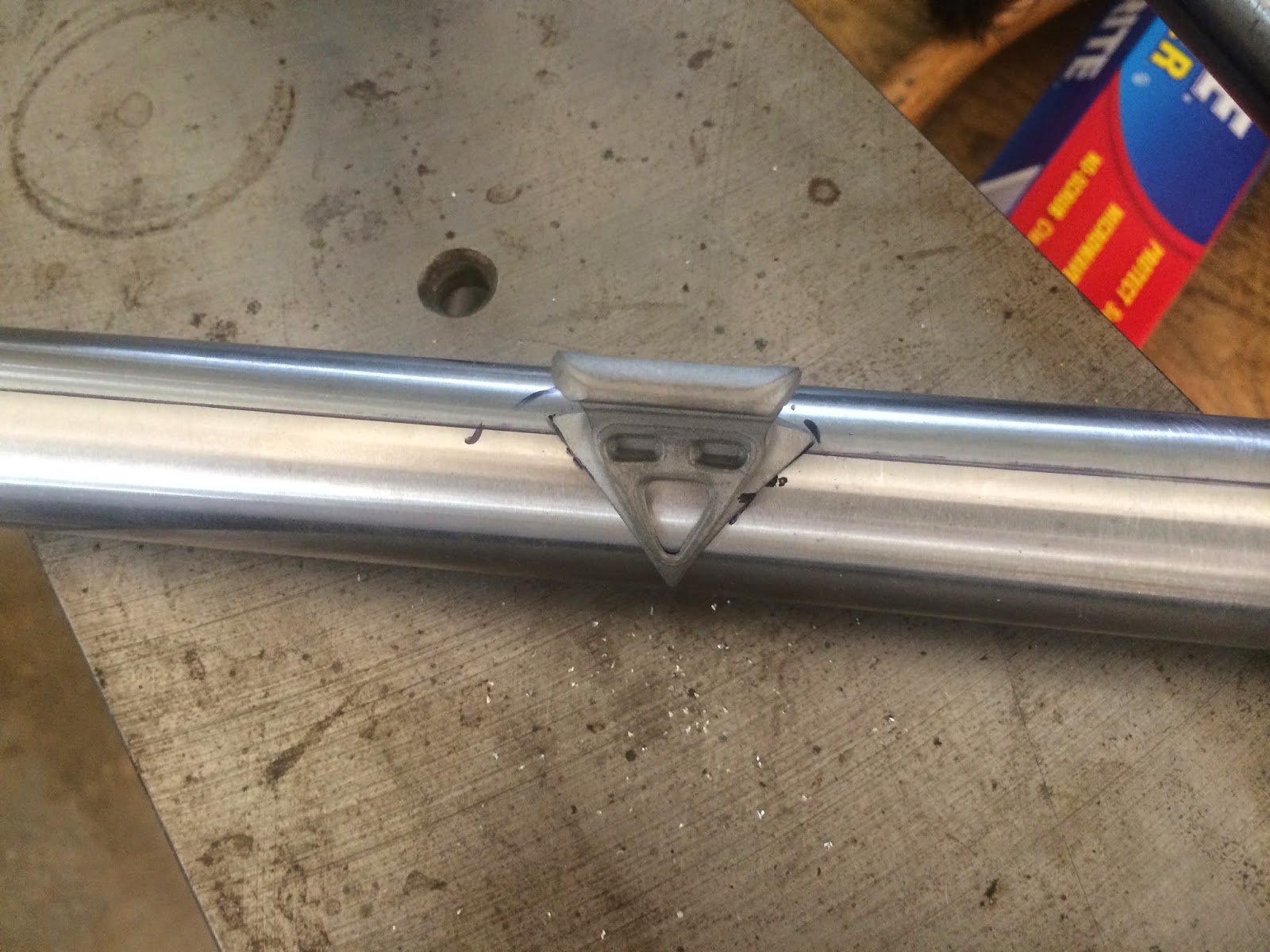
Water bottle and front derailleur mounts are installed prior to installing the tube.
A hole for the alignment pin on the front derailleur mount.
Note the pin.
Fluxed
Brazed
Ready to go
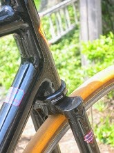
Filet braze between ST and BB
After filing and a little clean-up sanding with a small drum on a Dremal tool.
The lugs are supposed to be from the old Match factory. They're nice, and come in differing angles. This is the first time I'm using them, unfortunately, I only have 3 sets.
Finally, I'm slowly customizing my jig. Here is a wing nut replacing an Allen style cap screw. No longer do I have to find the Allen wrench prior to adjusting. This is on the backside of the ST support arm. It's so much quicker to mount/remove the ST now. A couple more wing nuts will be substituted at other locations.