This is doubly true with carbon fiber frames where small bits present some special challenges. I don't like to put lots of holes through my tubing, and I like to keep the holes as small as possible. The biggest challenge comes when a rider requests internal cable runs.
Routing of internal gear cables is dependent on the crank axle design. Some, like cartridge BBs, are hard to fit a cable around while staying within the BB. For these, I exit the cable at the base of the down tube and use a normal BB cable guide.
Where more space is available, however, its possible to do some interesting things. There are still some challenges however.
Many external cup BB's use a sleeve running around the axle and between the two cups. This isn't compatible with having shift cables inside the BB's. I've developed a split seal for inside the BB, where each bearing cup is sealed separately from the other - leaving a nice smooth axle around which the cable can turn on its run.
This opens up some neat possibilities. A large hole in the front of the BB allows the cable to run inside the down tube and directly into the BB. Then a whole at the rear of the BB has a cable tube running part way down the chain stay where it exits. The cable continues to a pre-formed housing stop - and through the housing to the rear derailer. This makes a very tidy looking setup.
For guides, I like 0.125" O.D. brass tube. This is easy to handle and requires a minimal hole through the tubing and chain stay.
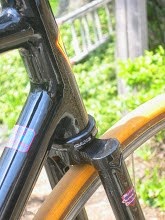
Here are some pix of the chain stay tubing exit that I'm working on. To begin, I build up a filet around the tube as it exits the chainstay.

The filet is basically a thickened epoxy which: 1) doesn't run while curing; 2) has better compression strength than plain epoxy. As you can see from the picture, its hard to get a smooth filet - it's too sticky.
The first thing we have to do is drill out the end of the tunnel and make sure that the cable passes freely through it.

Then we borrow some techniques from steel frame building. Out comes the file, and I file the filet into a smooth shape. It seems to be looking pretty good here, so now we can reinforce this area.
Frankly, this is probably not necessary, but this bike is being built to last and the chain stay encounters pretty significant forces on a regular basis.
In this case, I'm going to put on two longitudinal plys of uni-CF. Ea
 ch will be split in the middle, along its length, for about half its length. One will be laid from each direction, splitting around the exit hole. The splits allow me to better flatten the CF down, where I want it. These plys will wrap about 2/3 of the way down each side of the stay.
Next comes a uni-CF ply running directly around the stay (at 90 degrees to the prior stays). This ply won't be split, so our exit hole will be covered. Not to worry, it's easy to see where the hole is under the CF.
Finally, I'm putting a full wrap of my double layer 2x2 12K twill. This has a toughening layer between the two plys of CF, making it good for reinforcing a chain stay. The total reinforcement is 5 layers of 150 Gr/SqMeter CF - 3 uni, 2 low-crimp. When it's cured we'll need to drill out the exit hole and make sure all is smooth. Then this guid will be done. A similar arrangement will be used for the front derailer, but we can't finish it yet for reasons that will be obvious later.
Meanwhile, we need to squeeze our CF layers together, and remove the excess epoxy. This is a complicated area to work with. The part is small enough to easily fit in a vacuum bag. Given the small diameter of the chain stay, holding the plys together with good alignment, along with peel ply and bleeder felt, is a bit of a challenge. So for this situation I prefer a different approach - wrapping with electrical tape.
Before I begin wrapping plys of CF, I put a ring of electrical tape around the chain stay, just beyond each end of the section to be reinforced. The tape is wraped upside down - so the sticky side is out. These sections of tape will be used to start and end the compression wraps of tape. Mounting them before things are wet with epoxy makes it a much easier and cleaner step.

Once the CF sandwich is in place, I take off my gloves (so I have clean dry hands), and begin winding the tape around the stay. This too gets wrapped upside down - the inner (usually outer) side won't stick to the epoxy and by pulling the tape tightly, we get good compression.
Ultimately I wind from one end to the other, then reverse and wind back to the original end. Along the way, it's important to keep the tape as free from wrinkles as possible. Every wrinkle will cause a pocket of epoxy that needs to be later sanded down. And a big wrinkle could actually lead to a hump in the CF which would be nasty.
With this done, its time to poke lots of holes in the tape. Actually, in the course of wrapping, excess epoxy was driven ahead of the wrap and out of the layup. But we want to do more and the holes will allow more epoxy to migrate up and out of the CF. The whole setup gets heated by a nearby incandescent lamp to thin the epoxy and facilitate it's flow. If you click to enlarge the picture, you should see lots of little bubbles of epoxy on the surface of the tape.
I won't be able to return to this before tomorrow - but hopefully then I can show pictures of the raw finish.
Cheers,