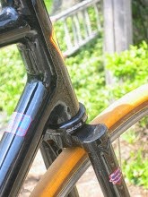
oh the stories they could tell. Today continued our outstanding weather - it feels like San Diego or something. With the day job starting late on Tuesdays, I scooted out for a quick ride on what is now called the Death Bike, which has some stories of its own.
Death Bike is a track bike, originally designed for one of our local racers. He, however, found a good deal on a used BH carbon frame and canceled right after the tubes were mitered. What the heck, the frame was only a little small for me, and I didn't have much time on a pure track bike design, so the build moved forward as my bike. Naturally, its set up as a fixed gear, but not like the path racer. The wheels are clincher, with 23mm open tubs from Deda - nice rolling tires. It has track forks with thick walled blades and limited rake making them stiff stiff stiff. The rest of the frame isn't much different being of 2 x oversize tubing (a 35mm steel downtube is a serious piece of pipe) - which combined with its black paint presents a very serious look.
Death Bike has relatively long trail given its steep head tube, because of the short fork rake. At slower speeds, trail quickly begins to stabilize the bike, but the steep head tube and short wheel base allow it to turn quickly and in a small space. Frankly, I think the geo is nailed for track riding. But it is a bit jarring on the streets, and there isn't room for cushier tires.
Death Bike had an old Campy mid-level (Athena?) brake on the front to keep me safe on the road. Yep, I drill the fork crown. But recently, a friend borrowed it to see if he liked fixed gear riding. For this, I swapped in a SRAM Force brake. That puppy offers right . . . NOW! stopping power - ideal for someone not used to only one brake. To simplify the brake change, I swapped in a new bar with a Cane Creek lever (leaving the old brake and bar connected to each other).
Anyhow, my rider has lots of time on fixed-gear training cycles, so I guessed he could make the step up to a fixed gear bike pretty easily. Whoops, I was wrong. Should have been there to give him pointers. Anyhow, he quickly got launched, twice, and decided fixed was not for him. Hence the name Death Bike.
The new handlebar is a Nitto Rando. I don't have much experience with these, so I was pleased to find that the shape was more comfortable than I expected. The Rando has a great bend behind the brake lever which supports the hand without leaning on the lever. This makes it ideal for a bike with only one brake lever, as both hands get support.
Today's ride pointed out that this is really a pretty stiff handlebar. Some folks take think of flex as a bad thing, but a softer bar offers more comfort than a stiff one. My ulnar nerve sometimes gives me trouble, making my hands/fingers numb. There are many factors related to this, but for me the primary ones are: fitness; & stiffness of the the bike's front end. At this point in the season, most bikes don't bother my ulnar: my weight is going into the pedals, not the bars. But, even on a short 1.5 hr ride, I experienced numb hands with the Rando on the Death Bike. Don't get me wrong, many other bars would do the same thing. But don't buy the Rando expecting it to enhance your bike's ride.
Both the roads & trails had light traffic this morning. Blue sky and temperatures in the mid-70's made for ideal conditions. I beat out a pretty good pace: both the frame and the wheels like to scoot. Meanwhile, my mind was liberated from serious thoughts. When I chose to consider it, I could tell that I was breathing hard and pushing the pace. But mostly, I just didn't notice. Other than the Ulnar thing, I could gone for hours at this level. Sort of a Zen thing - my mind and body all doing its thing in a very coordinated fashion, but without conscious thought driving any of it. I don't know if this makes sense to you, but its a cool thing when it happens.
That's it for today. Enjoy your rides. Pix of something soon.
Tuesday, September 15, 2009


Monday, September 14, 2009
Good Weather
Lots of work yesterday, but the weather was too nice to miss riding. I went out on the path racer (yeah I need to post some pix) this afternoon. It's always a peaceful bike to ride - even when pushed.
Along the way, some guy comes blasting out into the street, without looking, from a pedestrian path connecting to a residential neighborhood. He's all tricked out on his C'dale six/sixteen - and practically glowing with reflective bits from head to toe (despite it being a bright sunny afternoon).
A quick swerve avoids him, but the expected pass from behind never arrives. Half mile down is a stop for a busy road, and before I get across Mr. C'dale shows up. No problem, I'm just beginning to cross - but I get the feeling that he's right behind me and trying to pass. It's not a good spot for this as we are entering a trail with center barrier and a speed bump (both of which seem useless). So I keep my tempo up and the sound of him recedes as the path gets bumpy.
After a sharp turn onto another trail, and a street crossing, the trail scoots down a viaduct under the expressway, then it's back up and half a mile to the first street crossing. As I'm waiting to cross, guess who shows up and manages to time things perfectly to cross without stopping. All of which is cool, he ought to be making better time than me anyway.
But, once he's in front, he slows down. I'm not out for a race, but I like to maintain my cadence, and I can't just shift gears to adjust to his. The nice weather has brought out lots of slow riders, so passing is a bit chancy in many sections. Eventually the opportunity comes, and I'm off.
The next crossing has a stop light, and you can guess what happens. Instead of waiting for the light, I go ahead and time the traffic to shoot across before he can react. This time I up my tempo for a bit, build a gap and settle in. After a mile and a half he makes another dumb pass in heavy traffic. Naturally, as soon as we're in the clear, he slows down. So one more time I pass him, and stick to my cadence. It's a few more miles to the next crossing. While there's plenty of traffic, no one is trying dumb passes here. Cool, I get to relax and just enjoy peddling, with the subtle speed control that comes with a fixed (don't worry, I have front and rear brakes).
Before the next street, there are a couple of sharp corners. Ahead of them, I come upon a couple riding single file, a bit slowly. Judging distances, I can probably get around them before the corners, but it will be close enough that they might be scared, or pissed off. So I slow, and follow them through. And they slow more. As do I. And then they slow down even more. And so do I, again. Five-hundred feet begin to feel like a life sentence - but I'm staying cool.
Naturally, as we emerge from the trees, and try turn into the crossing, Mr. C-dale comes flying through, with total disregard for where each of us is, or where we are heading.
This time, I get to feeling pissy. Traffic holds us up from a quick crossing. At the gap, I take off but this time I spin it up and hold the up-tempo for a couple of miles. The sun is shining and the sky is clear and a bright blue. This portion of the trail rarely has much traffic, and is true to form today. While often less than 100 yards from the expressway, the path rises, dips, and winds through woods and past ponds. Its some of the best local scenery - it reminds me of Minnesota. Three miles of kicking it gets me to my 18 mile marker, and the beginning of loop around to start home. A few trails come together here, and with the expectation of traffic, I slow down.
Naturally I'm waiting for my shadow to jump out - but he doesn't. The last stretch must have finished him off. I return to my normal tempo. Fat tires (32mm), at 75psi, run quietly and absorb most of the bumps. The ride is mellow now. The light has a fall-like quality, even though all of nature is still green. The miles disappear without thought. The effort remains, but its natural - not something to notice.
People must be heading home, because I don't use either my voice or my bell for the rest of the way. Out on the roads, even the drivers seem to have chilled out. The air tempurature is in the upper seventies - its real short-sleeve weather. The three stop lights I pass are in sync with my ride- and the bike just spins on through.
Somehow, the messages are muted where I'm normally reminded that it's good to be almost home. And I spin along. Its fun to feel how happy the tires are when I do silly sharp turns. The garage door is up when arriving at my drive, and I coast right in. Opening the door to the house, I smell the first batch of chili for the season. It's a bit early, but smells great. The kids both have friends over, and are out back releasing there extra energy. I grab a shower no longer caring about missing today's Century. Instead, I'm ready to go back to work.
Along the way, some guy comes blasting out into the street, without looking, from a pedestrian path connecting to a residential neighborhood. He's all tricked out on his C'dale six/sixteen - and practically glowing with reflective bits from head to toe (despite it being a bright sunny afternoon).
A quick swerve avoids him, but the expected pass from behind never arrives. Half mile down is a stop for a busy road, and before I get across Mr. C'dale shows up. No problem, I'm just beginning to cross - but I get the feeling that he's right behind me and trying to pass. It's not a good spot for this as we are entering a trail with center barrier and a speed bump (both of which seem useless). So I keep my tempo up and the sound of him recedes as the path gets bumpy.
After a sharp turn onto another trail, and a street crossing, the trail scoots down a viaduct under the expressway, then it's back up and half a mile to the first street crossing. As I'm waiting to cross, guess who shows up and manages to time things perfectly to cross without stopping. All of which is cool, he ought to be making better time than me anyway.
But, once he's in front, he slows down. I'm not out for a race, but I like to maintain my cadence, and I can't just shift gears to adjust to his. The nice weather has brought out lots of slow riders, so passing is a bit chancy in many sections. Eventually the opportunity comes, and I'm off.
The next crossing has a stop light, and you can guess what happens. Instead of waiting for the light, I go ahead and time the traffic to shoot across before he can react. This time I up my tempo for a bit, build a gap and settle in. After a mile and a half he makes another dumb pass in heavy traffic. Naturally, as soon as we're in the clear, he slows down. So one more time I pass him, and stick to my cadence. It's a few more miles to the next crossing. While there's plenty of traffic, no one is trying dumb passes here. Cool, I get to relax and just enjoy peddling, with the subtle speed control that comes with a fixed (don't worry, I have front and rear brakes).
Before the next street, there are a couple of sharp corners. Ahead of them, I come upon a couple riding single file, a bit slowly. Judging distances, I can probably get around them before the corners, but it will be close enough that they might be scared, or pissed off. So I slow, and follow them through. And they slow more. As do I. And then they slow down even more. And so do I, again. Five-hundred feet begin to feel like a life sentence - but I'm staying cool.
Naturally, as we emerge from the trees, and try turn into the crossing, Mr. C-dale comes flying through, with total disregard for where each of us is, or where we are heading.
This time, I get to feeling pissy. Traffic holds us up from a quick crossing. At the gap, I take off but this time I spin it up and hold the up-tempo for a couple of miles. The sun is shining and the sky is clear and a bright blue. This portion of the trail rarely has much traffic, and is true to form today. While often less than 100 yards from the expressway, the path rises, dips, and winds through woods and past ponds. Its some of the best local scenery - it reminds me of Minnesota. Three miles of kicking it gets me to my 18 mile marker, and the beginning of loop around to start home. A few trails come together here, and with the expectation of traffic, I slow down.
Naturally I'm waiting for my shadow to jump out - but he doesn't. The last stretch must have finished him off. I return to my normal tempo. Fat tires (32mm), at 75psi, run quietly and absorb most of the bumps. The ride is mellow now. The light has a fall-like quality, even though all of nature is still green. The miles disappear without thought. The effort remains, but its natural - not something to notice.
People must be heading home, because I don't use either my voice or my bell for the rest of the way. Out on the roads, even the drivers seem to have chilled out. The air tempurature is in the upper seventies - its real short-sleeve weather. The three stop lights I pass are in sync with my ride- and the bike just spins on through.
Somehow, the messages are muted where I'm normally reminded that it's good to be almost home. And I spin along. Its fun to feel how happy the tires are when I do silly sharp turns. The garage door is up when arriving at my drive, and I coast right in. Opening the door to the house, I smell the first batch of chili for the season. It's a bit early, but smells great. The kids both have friends over, and are out back releasing there extra energy. I grab a shower no longer caring about missing today's Century. Instead, I'm ready to go back to work.
Thursday, July 16, 2009
Little Details make a custom frame
One of my current projects is a fast bike for someone who may yet try his hand at racing. I've been working with him to adjust his fit for some time now; and we're starting to see results. He's getting pretty quick on the bike, and can use much more handlebar drop than when we first started. That said, there's no way to get past the fact that he has an extreme body geometry where he needs about a 55CM seat-tube combined with 53CM top tube. And that's using a 9CM stem. You could say he's long in the leg.
He's a strong and heavy rider, so no wimpy frames for him. And it's going to be lugged steel. Now this presents some interesting issues. Generally, lug sets aren't available in multiple angles. So, framebuilders have to 'adjust' lugs to fit their designs.
For this frame, I've chosen Dazza's Slant Six (aka XL Compact) lugs with a Kirk Pacenti lugged Bottom Bracket. This combo is designed for use with a 2X Oversize tube set (in this case it'll be Columbus Life), with diameters as follows: DT=34.9mm, ST=31.8mm, TT=31.8mm. These fat tubes should keep everything plenty stiff. The Spirit chainstays will do their part to, running full size (i.e. without a taper) until the last 90mm. Most chainstays taper over the last 250-300mm - so this is a meaningful difference.
The Slant Six lugs create a frame with a modest slope (6 degrees) to the top tube, allowing for somewhat more standover clearance. Which is great. They are sized for a 1-1/8" steering tube - unlike most lugs which are sized for 1" steerers. Personally, I don't think that steerer diameter is very important for road bikes - but the rider wants a carbon fork and the larger steerer will leave us with more options.
So, back to the lugs, short top tube, and adjustments. The angles on the stock lower head tube lug, and on the BB between the seat and down tube, are about 3-1/2 degrees away from the plan on BikeCad. This means that it's time to adjust, in a fairly significant way.
I have some nice bending bars and quickly got the BB in shape. Naturally, the bent lug ports needs some hammering to make sure that they conformed to the shape of the tubes. The lower head tube lug is a bit more difficult. It is somewhat like a bikini lug, in that there isn't much lug on the headtube, especially above the down tube. This means that its hard to clamp this part of the lug in place during the bending, and that this section doesn't have enough material to both fill the gap created by the bend and provide a good surface area on the head tube. That's where this piece comes in. I traced the top of the lug onto a cutoff piece of head tube, and then cut it out.
This will get brazed into the corresponding section (see the second photo) of the lug, using brass filler. After some file work, it will fill the gap between the adjusted lug and the head tube. Some more filing on the outside of the lug will restore the outer shape (so that the shoreline of the lug doesn't become twice as thick).
The actual joint will be brazed with silver filler, hence it won't heat up enough to weaken the brass filler used to modify the lug. Cool concept but plenty of work.
That's it for this post. Cheers,b
He's a strong and heavy rider, so no wimpy frames for him. And it's going to be lugged steel. Now this presents some interesting issues. Generally, lug sets aren't available in multiple angles. So, framebuilders have to 'adjust' lugs to fit their designs.
For this frame, I've chosen Dazza's Slant Six (aka XL Compact) lugs with a Kirk Pacenti lugged Bottom Bracket. This combo is designed for use with a 2X Oversize tube set (in this case it'll be Columbus Life), with diameters as follows: DT=34.9mm, ST=31.8mm, TT=31.8mm. These fat tubes should keep everything plenty stiff. The Spirit chainstays will do their part to, running full size (i.e. without a taper) until the last 90mm. Most chainstays taper over the last 250-300mm - so this is a meaningful difference.
The Slant Six lugs create a frame with a modest slope (6 degrees) to the top tube, allowing for somewhat more standover clearance. Which is great. They are sized for a 1-1/8" steering tube - unlike most lugs which are sized for 1" steerers. Personally, I don't think that steerer diameter is very important for road bikes - but the rider wants a carbon fork and the larger steerer will leave us with more options.
So, back to the lugs, short top tube, and adjustments. The angles on the stock lower head tube lug, and on the BB between the seat and down tube, are about 3-1/2 degrees away from the plan on BikeCad. This means that it's time to adjust, in a fairly significant way.
I have some nice bending bars and quickly got the BB in shape. Naturally, the bent lug ports needs some hammering to make sure that they conformed to the shape of the tubes. The lower head tube lug is a bit more difficult. It is somewhat like a bikini lug, in that there isn't much lug on the headtube, especially above the down tube. This means that its hard to clamp this part of the lug in place during the bending, and that this section doesn't have enough material to both fill the gap created by the bend and provide a good surface area on the head tube.
 That's where this piece comes in. I traced the top of the lug onto a cutoff piece of head tube, and then cut it out.
This will get brazed into the corresponding section (see the second photo) of the lug, using brass filler. After some file work, it will fill the gap between the adjusted lug and the head tube. Some more filing on the outside of the lug will restore the outer shape (so that the shoreline of
 the lug doesn't become twice as thick).
The actual joint will be brazed with silver filler, hence it won't heat up enough to weaken the brass filler used to modify the lug. Cool concept but plenty of work.
That's it for this post. Cheers,b
Tuesday, July 07, 2009
They said what?
Its become clear to me that I shouldn't promise anything here - something always comes up to distract the dialog. So no promises, I think.
There many topics worthy of discussion, but what got me going tonight was this bit in Velo News
Now, I don't know about you, but I think big companies try to patent too much - especially broad concepts which they haven't invented or substantially developed. I think that Trek's 'Kamm Tail' fits this description. First of all, they are borrowing aerodynamic licks that have been employed repeatedly, for many years, and in a borad variety contexts - it's nothing new. And applying them to a bicycle isn't nothing new.
In fact, I've been experimenting with similar tubing shapes on TT bikes for over a year. And I didn't get the idea from Trek or anyone else in the bike business. In fact, I've long wondered why the so-called aerodynamicsts of the bike industry weren't exploring these ideas all along - thus making me wonder how many of them really know anything about aerodynamics.
It should be noted that an 8:1 aspect ratio is not optimal (as described in the article) for head-on air pressue. 8:1 represents a 12.5% ratio, which is near the maximum for the size of airfoil created by a bicycle tube, and the speeds at which a bike travels. Airfoils have scaling issues, and the smaller the airfoil is, the greater the challenges presented. If we want to talk about an optimal aspect ratio for dead-ahead air pressure, then we should be looking to something in the 8-10% range, meaning somewhere between 10:1 and 12:1. These are significantly different form an 8:1 ratio.
Of course, it's not just aspect ratio, but also the shape and size of the object which determines how slippery the object is. A really big object with a very slippery shape and aspect ratio may have more drag than a smaller object which has a sticky shape and aspect ratio. Or it may not. So much more needs to be pinned down, apart from the 8:1 ratio. But lets explore this further.
First, a round tube isn't much better than a square tube regarding the drag produced as an air stream hits it. Historically, metal aero-tubes had a round front and tapered rear. The rear fairing did little to improve aerodynamics over a normal round tube (although it never stopped a manufacturer from touting aero advantages). The simple learning here is that the leading edge (front) of the tube is the most critical shape for achieving low aero drag.
Trek suggests that the tube's profile should/can be cut off just past its broadest point. So let's look at this with their 8:1 profile and the UCI limit of 3:1 size.
Usually the thickest part of a wing is about 1/3 back from the leading edge. On an 8:1 ratio tube, with a 1" thickness, the chord (front to back distance) would be 8". If we took only the front 1/3 of that shape, the actual (as opposed to effective) chord would be reduced to 2-2/3". This creates a tube with a 1:2-2/3 aspect ratio. Which keeps us in the game vis a vis UCI rules. So far, so good.
Now lets talk about the Kamm Tail. The concept of the Kamm Tail (or more correctly Kamm Back) is that an aerodynamic automobile not only has too little aerodynamic downforce for stability, but actually can achieve aerodynamic lift as speed. The Kamm Back creates a low pressure area behind the vehicle (drag) which helps to maintain directional stability. So, while it works in conjunction with aerodynamic drag reduction, it actually is using drag to keep a car traveling in the correct direction. Which is quite different from what Trek is describing.
This doesn't make Trek's shapes or concept wrong, but shows how marketing mis-uses technology to explain and sell products.
OK, so let's get back to this shape thing. It looks like Trek has 1/3 of an inch left according to UCI rules. Should they max out the 3:1 ratio?
Aerodynamics occur in 3 dimensions. Any aerodynamicist who forgets this is unlikely to be successful for long. For example, a round down tube has a salami slice like shape (sort of an oval) as it presents itself to the wind - because the tube isn't vertical.
Moreover, the airflow will chase the lowest pressure areas. As with a swept wing on a jet, this means that on the downtube, there will be airflow from the further forward points (near the head tube) towards the bottom bracket - all else being equal. Perhaps you've seen an airplane with tiplets on the ends of the wing - they often look like small rudders. On the wing, air travels similarly down its length. Air below the wing has higher pressure than on top - so when the flow of air reaches the end of the wing, the high pressure below wants to flip over the top and fill the low-pressure area. This reduces lift and causes drag. The tiplet is designed to interfere with the spill of high pressure are from the bottom to the top, thus improving lift and reducing drag.
The sides of the downtube are symmetrical. So, if the wind is from dead-ahead, then there won't be a high and low pressure side. Nonetheless, all else being equal, the air flow along the downtube will be slightly downhill - which further elongates the oval presented to the wind.
It's possible that a tube that has a actual 3:1 ratio, presents itself to the wind at some other ratio - for example, instead of being 3" deep aerodynamically, it might be 4" long. Now this is of no particular advantage to one builder or another - they will all have a chance to leverage this phenomena. But it does prepare us for the next step.
Unlike what Trek says, the optimal cutoff for the airfoil is not at its widest point. The airflow needs to be stablized into a path similar to that it would take if the rear of the foil had not been truncated. The path from the thickes part of a wing to it's trailing edge is not a straight path. But it is generally the straightest part of the outline of the airfoil. Let's say that when we truncate an airfoil, we still need 10% of the overall chord length to be located behind the widest point of the airfoil. In reality, how much wing is required behind the maximum thickness is a function of the wing size, shape, and airspeed - so we're speaking in hypotheticals here when we use the numbe 10%.
Given that the base airfoil is 8:1 (per Trek), the 10% extra would be 0.8". Now, measured using the actual tube profile, we have a chord lenght of 2.667". Adding 0.8" to this gives us a chord of 3.467" - or an aspect ratio of almost 3.5:1 - well above the UCI limits. But let's think this over again. Assuming that we present a foil to the wind that is 4" deep and 1" wide, for a tube that has an actual 3:1 profile: In this case we have more of the aerodynamic airfoil with which to play. Let's move the widest point of the tube forward, so that it is 2.667" behind the leading edge when measured along the path of air flow. That means that we have 1.333" left behind the widest point, and this 1.333" is 13% of the original air foils chord. If we only needed 10% of the overall chord behind the widest point, then we have another 3% to play with.
Let me point out that the numbers above are not meant to emulate the reality of Trek's tube shape. Rather, they give the reader some insight into the sorts of opportunities and tradeoffs which exist in designing a an efficiently shaped downtube.
Now, if we have 3% of the chord left to play with, what should we do with this? If the wind always came from the front, we would probably just use it to truncate the shape closer to the trailing edge. However, the wind rarely is truely from directly ahead. All the points of the compass have equal likelyhood has being the source of any wind, and while the bike's ground movement adds another vector necessary to calculate effective (as opposed to true) wind direction, it should be obvious that we will commonly contend with a wind that is not from dead ahead. Further componding things this challenge is the fact that a bike rarely travels in a truely straight line. Instead bike and rider are constantly adjusting inputs, causing the front end to continually move back and forth.
So what? Think of our truncated airfoil. With wind dead ahead, a sharp corner at the rear has little impact. But, turn the wind direction 15 degrees to one side, and now this corner becomes a drag riser. We want to smooth the transition of the air flowing around this edge. A rounder shape will work better in these circumstances. So, the extra 3/10" in chord length might be best used to transition air around the rear of the tube, when its coming from a direction other than straight ahead.
With the widest part of the tube being located 2.667" from the leading edge, along the actual airflow, where is it located in a 90 degree cross section of the tube? Well, its 2.667/4.0 from the front. Solving the math gives us a maximum width 2" from the front of the tube. Similarly, the end of the rearward taper is located 2.600" inches back, leaving 0.4" that can be shaped to help cross winds get around the rear of the tube. All of this has been down in the context of UCI 3:1 rule.
Naturally, this isn't the end of the story. For example, cross winds see an assymetric shape, even though the tube is symmetric from left to right. This begs the question regarding whether there might be benefits to having a tube which is symmetric from front to back? Also, there are aerodynamic tools which can manange how well the airflow follows the contour of the airfoil. Remember when we (arbitrarily) suggested that the tube shape needed to include 10% of the overall (8") chord located behind the widest point of our tube? Flow managing tools could reduce this number without limiting our drag reduction. If so, then we would have more chord length available (within UCI rules) by which to manage how cross winds wrap around the down tube. And, what if there is another place where we can truncate the chord of the tube without compromizing aerodynamics? There is such a place, but that's a story for a different day.
Be aware, Trek is sloppy in describing what they are doing, greeding in suggesting that they may patent their technology, most likely accurate in describing what they doing as an improvement, and not producing an impact that you can measure within margins of error in real practice. Yeah, we haven't touched on this yet, but you the rider are the source aero drag. Yes the bike contributes, but its contribution is small. Your position on the bike; what accessories (water bottle(s), computer, tool bag, etc.) and how carry them; these are the important aspects of aerodynamics. Until you have these nailed, don't worry about the shape of your frame tubes, or how well hidden your brake may be.
Until next time, Cheers!
Rick
There many topics worthy of discussion, but what got me going tonight was this bit in Velo News
Now, I don't know about you, but I think big companies try to patent too much - especially broad concepts which they haven't invented or substantially developed. I think that Trek's 'Kamm Tail' fits this description. First of all, they are borrowing aerodynamic licks that have been employed repeatedly, for many years, and in a borad variety contexts - it's nothing new. And applying them to a bicycle isn't nothing new.
In fact, I've been experimenting with similar tubing shapes on TT bikes for over a year. And I didn't get the idea from Trek or anyone else in the bike business. In fact, I've long wondered why the so-called aerodynamicsts of the bike industry weren't exploring these ideas all along - thus making me wonder how many of them really know anything about aerodynamics.
It should be noted that an 8:1 aspect ratio is not optimal (as described in the article) for head-on air pressue. 8:1 represents a 12.5% ratio, which is near the maximum for the size of airfoil created by a bicycle tube, and the speeds at which a bike travels. Airfoils have scaling issues, and the smaller the airfoil is, the greater the challenges presented. If we want to talk about an optimal aspect ratio for dead-ahead air pressure, then we should be looking to something in the 8-10% range, meaning somewhere between 10:1 and 12:1. These are significantly different form an 8:1 ratio.
Of course, it's not just aspect ratio, but also the shape and size of the object which determines how slippery the object is. A really big object with a very slippery shape and aspect ratio may have more drag than a smaller object which has a sticky shape and aspect ratio. Or it may not. So much more needs to be pinned down, apart from the 8:1 ratio. But lets explore this further.
First, a round tube isn't much better than a square tube regarding the drag produced as an air stream hits it. Historically, metal aero-tubes had a round front and tapered rear. The rear fairing did little to improve aerodynamics over a normal round tube (although it never stopped a manufacturer from touting aero advantages). The simple learning here is that the leading edge (front) of the tube is the most critical shape for achieving low aero drag.
Trek suggests that the tube's profile should/can be cut off just past its broadest point. So let's look at this with their 8:1 profile and the UCI limit of 3:1 size.
Usually the thickest part of a wing is about 1/3 back from the leading edge. On an 8:1 ratio tube, with a 1" thickness, the chord (front to back distance) would be 8". If we took only the front 1/3 of that shape, the actual (as opposed to effective) chord would be reduced to 2-2/3". This creates a tube with a 1:2-2/3 aspect ratio. Which keeps us in the game vis a vis UCI rules. So far, so good.
Now lets talk about the Kamm Tail. The concept of the Kamm Tail (or more correctly Kamm Back) is that an aerodynamic automobile not only has too little aerodynamic downforce for stability, but actually can achieve aerodynamic lift as speed. The Kamm Back creates a low pressure area behind the vehicle (drag) which helps to maintain directional stability. So, while it works in conjunction with aerodynamic drag reduction, it actually is using drag to keep a car traveling in the correct direction. Which is quite different from what Trek is describing.
This doesn't make Trek's shapes or concept wrong, but shows how marketing mis-uses technology to explain and sell products.
OK, so let's get back to this shape thing. It looks like Trek has 1/3 of an inch left according to UCI rules. Should they max out the 3:1 ratio?
Aerodynamics occur in 3 dimensions. Any aerodynamicist who forgets this is unlikely to be successful for long. For example, a round down tube has a salami slice like shape (sort of an oval) as it presents itself to the wind - because the tube isn't vertical.
Moreover, the airflow will chase the lowest pressure areas. As with a swept wing on a jet, this means that on the downtube, there will be airflow from the further forward points (near the head tube) towards the bottom bracket - all else being equal. Perhaps you've seen an airplane with tiplets on the ends of the wing - they often look like small rudders. On the wing, air travels similarly down its length. Air below the wing has higher pressure than on top - so when the flow of air reaches the end of the wing, the high pressure below wants to flip over the top and fill the low-pressure area. This reduces lift and causes drag. The tiplet is designed to interfere with the spill of high pressure are from the bottom to the top, thus improving lift and reducing drag.
The sides of the downtube are symmetrical. So, if the wind is from dead-ahead, then there won't be a high and low pressure side. Nonetheless, all else being equal, the air flow along the downtube will be slightly downhill - which further elongates the oval presented to the wind.
It's possible that a tube that has a actual 3:1 ratio, presents itself to the wind at some other ratio - for example, instead of being 3" deep aerodynamically, it might be 4" long. Now this is of no particular advantage to one builder or another - they will all have a chance to leverage this phenomena. But it does prepare us for the next step.
Unlike what Trek says, the optimal cutoff for the airfoil is not at its widest point. The airflow needs to be stablized into a path similar to that it would take if the rear of the foil had not been truncated. The path from the thickes part of a wing to it's trailing edge is not a straight path. But it is generally the straightest part of the outline of the airfoil. Let's say that when we truncate an airfoil, we still need 10% of the overall chord length to be located behind the widest point of the airfoil. In reality, how much wing is required behind the maximum thickness is a function of the wing size, shape, and airspeed - so we're speaking in hypotheticals here when we use the numbe 10%.
Given that the base airfoil is 8:1 (per Trek), the 10% extra would be 0.8". Now, measured using the actual tube profile, we have a chord lenght of 2.667". Adding 0.8" to this gives us a chord of 3.467" - or an aspect ratio of almost 3.5:1 - well above the UCI limits. But let's think this over again. Assuming that we present a foil to the wind that is 4" deep and 1" wide, for a tube that has an actual 3:1 profile: In this case we have more of the aerodynamic airfoil with which to play. Let's move the widest point of the tube forward, so that it is 2.667" behind the leading edge when measured along the path of air flow. That means that we have 1.333" left behind the widest point, and this 1.333" is 13% of the original air foils chord. If we only needed 10% of the overall chord behind the widest point, then we have another 3% to play with.
Let me point out that the numbers above are not meant to emulate the reality of Trek's tube shape. Rather, they give the reader some insight into the sorts of opportunities and tradeoffs which exist in designing a an efficiently shaped downtube.
Now, if we have 3% of the chord left to play with, what should we do with this? If the wind always came from the front, we would probably just use it to truncate the shape closer to the trailing edge. However, the wind rarely is truely from directly ahead. All the points of the compass have equal likelyhood has being the source of any wind, and while the bike's ground movement adds another vector necessary to calculate effective (as opposed to true) wind direction, it should be obvious that we will commonly contend with a wind that is not from dead ahead. Further componding things this challenge is the fact that a bike rarely travels in a truely straight line. Instead bike and rider are constantly adjusting inputs, causing the front end to continually move back and forth.
So what? Think of our truncated airfoil. With wind dead ahead, a sharp corner at the rear has little impact. But, turn the wind direction 15 degrees to one side, and now this corner becomes a drag riser. We want to smooth the transition of the air flowing around this edge. A rounder shape will work better in these circumstances. So, the extra 3/10" in chord length might be best used to transition air around the rear of the tube, when its coming from a direction other than straight ahead.
With the widest part of the tube being located 2.667" from the leading edge, along the actual airflow, where is it located in a 90 degree cross section of the tube? Well, its 2.667/4.0 from the front. Solving the math gives us a maximum width 2" from the front of the tube. Similarly, the end of the rearward taper is located 2.600" inches back, leaving 0.4" that can be shaped to help cross winds get around the rear of the tube. All of this has been down in the context of UCI 3:1 rule.
Naturally, this isn't the end of the story. For example, cross winds see an assymetric shape, even though the tube is symmetric from left to right. This begs the question regarding whether there might be benefits to having a tube which is symmetric from front to back? Also, there are aerodynamic tools which can manange how well the airflow follows the contour of the airfoil. Remember when we (arbitrarily) suggested that the tube shape needed to include 10% of the overall (8") chord located behind the widest point of our tube? Flow managing tools could reduce this number without limiting our drag reduction. If so, then we would have more chord length available (within UCI rules) by which to manage how cross winds wrap around the down tube. And, what if there is another place where we can truncate the chord of the tube without compromizing aerodynamics? There is such a place, but that's a story for a different day.
Be aware, Trek is sloppy in describing what they are doing, greeding in suggesting that they may patent their technology, most likely accurate in describing what they doing as an improvement, and not producing an impact that you can measure within margins of error in real practice. Yeah, we haven't touched on this yet, but you the rider are the source aero drag. Yes the bike contributes, but its contribution is small. Your position on the bike; what accessories (water bottle(s), computer, tool bag, etc.) and how carry them; these are the important aspects of aerodynamics. Until you have these nailed, don't worry about the shape of your frame tubes, or how well hidden your brake may be.
Until next time, Cheers!
Rick
Sunday, November 23, 2008
Cable Runs
Something that new framebuilders should learn sooner rather than later is that planning and installing small bits (cable guides, brake mounts, H2O mounts, etc.) are better done up front rather than after the frame is built.
This is doubly true with carbon fiber frames where small bits present some special challenges. I don't like to put lots of holes through my tubing, and I like to keep the holes as small as possible. The biggest challenge comes when a rider requests internal cable runs.
Routing of internal gear cables is dependent on the crank axle design. Some, like cartridge BBs, are hard to fit a cable around while staying within the BB. For these, I exit the cable at the base of the down tube and use a normal BB cable guide.
Where more space is available, however, its possible to do some interesting things. There are still some challenges however.
Many external cup BB's use a sleeve running around the axle and between the two cups. This isn't compatible with having shift cables inside the BB's. I've developed a split seal for inside the BB, where each bearing cup is sealed separately from the other - leaving a nice smooth axle around which the cable can turn on its run.
This opens up some neat possibilities. A large hole in the front of the BB allows the cable to run inside the down tube and directly into the BB. Then a whole at the rear of the BB has a cable tube running part way down the chain stay where it exits. The cable continues to a pre-formed housing stop - and through the housing to the rear derailer. This makes a very tidy looking setup.
For guides, I like 0.125" O.D. brass tube. This is easy to handle and requires a minimal hole through the tubing and chain stay.
Here are some pix of the chain stay tubing exit that I'm working on. To begin, I build up a filet around the tube as it exits the chainstay.

The filet is basically a thickened epoxy which: 1) doesn't run while curing; 2) has better compression strength than plain epoxy. As you can see from the picture, its hard to get a smooth filet - it's too sticky.
The first thing we have to do is drill out the end of the tunnel and make sure that the cable passes freely through it.

Then we borrow some techniques from steel frame building. Out comes the file, and I file the filet into a smooth shape. It seems to be looking pretty good here, so now we can reinforce this area.
Frankly, this is probably not necessary, but this bike is being built to last and the chain stay encounters pretty significant forces on a regular basis.
In this case, I'm going to put on two longitudinal plys of uni-CF. Ea ch will be split in the middle, along its length, for about half its length. One will be laid from each direction, splitting around the exit hole. The splits allow me to better flatten the CF down, where I want it. These plys will wrap about 2/3 of the way down each side of the stay.
Next comes a uni-CF ply running directly around the stay (at 90 degrees to the prior stays). This ply won't be split, so our exit hole will be covered. Not to worry, it's easy to see where the hole is under the CF.
Finally, I'm putting a full wrap of my double layer 2x2 12K twill. This has a toughening layer between the two plys of CF, making it good for reinforcing a chain stay. The total reinforcement is 5 layers of 150 Gr/SqMeter CF - 3 uni, 2 low-crimp. When it's cured we'll need to drill out the exit hole and make sure all is smooth. Then this guid will be done. A similar arrangement will be used for the front derailer, but we can't finish it yet for reasons that will be obvious later.
Meanwhile, we need to squeeze our CF layers together, and remove the excess epoxy. This is a complicated area to work with. The part is small enough to easily fit in a vacuum bag. Given the small diameter of the chain stay, holding the plys together with good alignment, along with peel ply and bleeder felt, is a bit of a challenge. So for this situation I prefer a different approach - wrapping with electrical tape.
Before I begin wrapping plys of CF, I put a ring of electrical tape around the chain stay, just beyond each end of the section to be reinforced. The tape is wraped upside down - so the sticky side is out. These sections of tape will be used to start and end the compression wraps of tape. Mounting them before things are wet with epoxy makes it a much easier and cleaner step.

Once the CF sandwich is in place, I take off my gloves (so I have clean dry hands), and begin winding the tape around the stay. This too gets wrapped upside down - the inner (usually outer) side won't stick to the epoxy and by pulling the tape tightly, we get good compression.
Ultimately I wind from one end to the other, then reverse and wind back to the original end. Along the way, it's important to keep the tape as free from wrinkles as possible. Every wrinkle will cause a pocket of epoxy that needs to be later sanded down. And a big wrinkle could actually lead to a hump in the CF which would be nasty.
With this done, its time to poke lots of holes in the tape. Actually, in the course of wrapping, excess epoxy was driven ahead of the wrap and out of the layup. But we want to do more and the holes will allow more epoxy to migrate up and out of the CF. The whole setup gets heated by a nearby incandescent lamp to thin the epoxy and facilitate it's flow. If you click to enlarge the picture, you should see lots of little bubbles of epoxy on the surface of the tape.
I won't be able to return to this before tomorrow - but hopefully then I can show pictures of the raw finish.
Cheers,
This is doubly true with carbon fiber frames where small bits present some special challenges. I don't like to put lots of holes through my tubing, and I like to keep the holes as small as possible. The biggest challenge comes when a rider requests internal cable runs.
Routing of internal gear cables is dependent on the crank axle design. Some, like cartridge BBs, are hard to fit a cable around while staying within the BB. For these, I exit the cable at the base of the down tube and use a normal BB cable guide.
Where more space is available, however, its possible to do some interesting things. There are still some challenges however.
Many external cup BB's use a sleeve running around the axle and between the two cups. This isn't compatible with having shift cables inside the BB's. I've developed a split seal for inside the BB, where each bearing cup is sealed separately from the other - leaving a nice smooth axle around which the cable can turn on its run.
This opens up some neat possibilities. A large hole in the front of the BB allows the cable to run inside the down tube and directly into the BB. Then a whole at the rear of the BB has a cable tube running part way down the chain stay where it exits. The cable continues to a pre-formed housing stop - and through the housing to the rear derailer. This makes a very tidy looking setup.
For guides, I like 0.125" O.D. brass tube. This is easy to handle and requires a minimal hole through the tubing and chain stay.
Here are some pix of the chain stay tubing exit that I'm working on. To begin, I build up a filet around the tube as it exits the chainstay.

The filet is basically a thickened epoxy which: 1) doesn't run while curing; 2) has better compression strength than plain epoxy. As you can see from the picture, its hard to get a smooth filet - it's too sticky.
The first thing we have to do is drill out the end of the tunnel and make sure that the cable passes freely through it.

Then we borrow some techniques from steel frame building. Out comes the file, and I file the filet into a smooth shape. It seems to be looking pretty good here, so now we can reinforce this area.
Frankly, this is probably not necessary, but this bike is being built to last and the chain stay encounters pretty significant forces on a regular basis.
In this case, I'm going to put on two longitudinal plys of uni-CF. Ea
 ch will be split in the middle, along its length, for about half its length. One will be laid from each direction, splitting around the exit hole. The splits allow me to better flatten the CF down, where I want it. These plys will wrap about 2/3 of the way down each side of the stay.
Next comes a uni-CF ply running directly around the stay (at 90 degrees to the prior stays). This ply won't be split, so our exit hole will be covered. Not to worry, it's easy to see where the hole is under the CF.
Finally, I'm putting a full wrap of my double layer 2x2 12K twill. This has a toughening layer between the two plys of CF, making it good for reinforcing a chain stay. The total reinforcement is 5 layers of 150 Gr/SqMeter CF - 3 uni, 2 low-crimp. When it's cured we'll need to drill out the exit hole and make sure all is smooth. Then this guid will be done. A similar arrangement will be used for the front derailer, but we can't finish it yet for reasons that will be obvious later.
Meanwhile, we need to squeeze our CF layers together, and remove the excess epoxy. This is a complicated area to work with. The part is small enough to easily fit in a vacuum bag. Given the small diameter of the chain stay, holding the plys together with good alignment, along with peel ply and bleeder felt, is a bit of a challenge. So for this situation I prefer a different approach - wrapping with electrical tape.
Before I begin wrapping plys of CF, I put a ring of electrical tape around the chain stay, just beyond each end of the section to be reinforced. The tape is wraped upside down - so the sticky side is out. These sections of tape will be used to start and end the compression wraps of tape. Mounting them before things are wet with epoxy makes it a much easier and cleaner step.

Once the CF sandwich is in place, I take off my gloves (so I have clean dry hands), and begin winding the tape around the stay. This too gets wrapped upside down - the inner (usually outer) side won't stick to the epoxy and by pulling the tape tightly, we get good compression.
Ultimately I wind from one end to the other, then reverse and wind back to the original end. Along the way, it's important to keep the tape as free from wrinkles as possible. Every wrinkle will cause a pocket of epoxy that needs to be later sanded down. And a big wrinkle could actually lead to a hump in the CF which would be nasty.
With this done, its time to poke lots of holes in the tape. Actually, in the course of wrapping, excess epoxy was driven ahead of the wrap and out of the layup. But we want to do more and the holes will allow more epoxy to migrate up and out of the CF. The whole setup gets heated by a nearby incandescent lamp to thin the epoxy and facilitate it's flow. If you click to enlarge the picture, you should see lots of little bubbles of epoxy on the surface of the tape.
I won't be able to return to this before tomorrow - but hopefully then I can show pictures of the raw finish.
Cheers,
Friday, November 21, 2008
Done Baking

Here's the main plate. This is viewed from the top and looks much like the surface of the last piece. However, when we turn it over, we'll see a different finish.
Unfortunately, there are a couple of defects on the bottom. Most obvious, a corner got folded over, apparently while placing the layup in the vacuum bag.

While not visible in the pictures, a close observation shows the defect visible through the top layer as a triangular corner which is lower than the rest of the plate.
There is also a stray fiber that got caught - which is strictly a cosmetic defect. But there are also some depressions in the bottom - apparently the table had some defects in its surface which I didn't detect.
All of t
 his leads me to consider a different approach for the next time. Rather than using a bag on a table, I'm going to try laying a piece of plate glass on the table. This should provide a smooth lower surface. The layout w/ peelplys and breathers will be laid on this. Then a lay piece of bagging material over this and seal its edges to the table with a special caulk-like tape. This will avoid the difficulty of sliding the layup into the bag.
Having said this, the majority of this plate looks good, and should make some fine dropouts.
All up this plate weighs 310 grams - so 40 grams of epoxy was squeezed out in the vacuum. That said, my ideal weight was 250 grams and my realistic expectation was 290 grams. So we're just a bit pudgy. It seems clear that I started with too much epoxy to hit my targets. Also, I need to check my pressure next time to make sure that I'm pulling as much as I think (possibility of excess leakage in the bag). Nonetheless, this plate came in with a lower epoxy weight than the last plate so we're making progress. And there doesn't appear to be so much epoxy as to reduce the strength of the plate.
More later.
More Carbon Plates


Pictures! Yea!!!!
Sorry for the quality, its a very old digital camera and the color is off because these were taken without a flash.
Anyhow, these are some more carbon fiber plates under vacuum. Last time, some heavy Kevlar was applied where the axle nuts rest. Two problems with this: 1) It doesn't cut; 2) It doesn't cut. A $35 ceramic tile blade died in the jig saw trying to cut Kevlar. Note, it didn't have any problem getting through the CF - slow steady cuts worked great. Moreover, the edges of the Kevlar end up fraying where the saw tore through them - very unsightly. Meanwhile, some of the CF elders suggested that I experiment without and protective layer over the CF - so that's what I'm doing here.
The last plates were cut up into smaller pieces and showed now voids or soft spots - clearly the epoxy soaked through just fine. After some careful weighing of my raw CF stocks, and some further calculations, it appears that I added nearly 70% epoxy by weight to the final product. That's fine, but not as light as it can be. It may be that for this sort of heavy layup, and infusion technique might be best. Something to explore down the line.
Back to the pix (you can click on them to enlarge), you can see the rough outline of the larger plate being vacuumed. In the one picture, you can also see a 2x4 clamped down on top of the other plate - squeezing it to the work table.
This time my layups looked much dryer than last - but after weighing everything, the main plate has 175 grams of CF and had 175 grams of epoxy added. Once its cured, we'll weigh the plate and find out how much epoxy remained in it. I'm hoping that this will be lighter (by volume) than the last.
The hidden (by the board) plate is just a lever about 1" x 7mm (finished thickness) x 12". It'll be used for some deflection testing.
The main plate will be used for some sample dropouts and the remainder will be used for a variety of tests, including impact & tensile strength.
For this set of plates, a release film was used on the bottom side instead of a peel-ply fabric. This should lead to a layer of smooth epoxy - although nothing like a jell coat. So it's just an experiment. Just as the clamps on the narrow plate are an experiment.
You can see the dark spots where the epoxy is oozing through. Apart from the edges, there's not too much. I gave the edges an extra drink just because I apply epoxy from the center and they looked a bit dryer. Maybe next time we'll do with out the extra.
Just FYI, there is a bleeder felt under the whole setup
(inside the bag of course), and one over the top. The long edges of the big plate got an extra layer of bleeder on top - you can see the ridges running across the top of the bag where these end. You'll also note that the bleeder is much wider than the plates - so there should always be an unobstructed path for the air to reach the outlets for the vacuum pump.
That's about it for this time. See ya around.
Friday, October 24, 2008
CF Drop Outs
OK,
I'm working on CF dropouts. I want to use a new brand of rear triangles, but they don't work with any prefabbed DOs. This is because the chainstays taper all the way to the ends, which aren't parallel to each other. So, a round plug that fits into the end, is way to loose at its front. And, a Do that follows the axis of the stay, without a bend, won't form a parallel platform for the hub.
Anyhow, the first step is to make a plate from which to cut out the DOs. Luckly, I've come into some samples of very nice CF fabrics. The one that will be the base of the plate has 9 plys of UNI Cf in 0/90/45/-45 degree orientation. Three layers of this are used, creating a base 27 layers deep. On the outside, I'm using some 2x2 12K twill that is doubled layered, so the total sandwich will be 31 layers. Kevlar tape goes on where the axle mounts to protect the CF from the bolts.
So here are some pictures from my first plate. This is the backside - nice and flat with a stray piece of CF in the laminate. Unless this stray ends up in an exposed place, I won't worry about it. Note, the Kevlar hasn't been mounted on this side yet. That will wait until the DOs are cut out.
The next view is an edge of the CF that has been cut. All looks good from this slice in terms of bonding and compaction.
You can click on the pictures to enlarge them.
 No indications of voids or dry spots. This whole plate weighs 65 grams. I expect that the dropouts will weight less than half this - say 30 grams. After adding the hardware for the derailer - it'll probably be 35 grams.
Typical aluminum DOs the come with many carbon rear triangles weigh around 110 grams (on my scale).
The stainless plate DOs that these are based on weigh in at 125 grams.
So, 35 grams for these sounds pretty good to me.
By the way, Blogger is turning my pix sideways for some reason - sorry.
Here's the front. I've laid the stainless DOs on top of the plate, then sprayed it with some gray primer - to show where to cut.
The yellow is the Kevlar. One piece of Kevlar picked up a spare piece of CF - but this will sand out easily enough.
Notice on the derailer side how there is a shiny rectangle. There was a bit of tape on the end of the Kevlar tape to prevent fraying. The rest of the material was pressed against a woven peel-ply - leaving a flat finish. Where the tape was left a glossy finish.
That's it for tonight. See ya next time.
I'm working on CF dropouts. I want to use a new brand of rear triangles, but they don't work with any prefabbed DOs. This is because the chainstays taper all the way to the ends, which aren't parallel to each other. So, a round plug that fits into the end, is way to loose at its front. And, a Do that follows the axis of the stay, without a bend, won't form a parallel platform for the hub.
Anyhow, the first step is to make a plate from which to cut out the DOs. Luckly, I've come into some samples of very nice CF fabrics. The one that will be the base of the plate has 9 plys of UNI Cf in 0/90/45/-45 degree orientation. Three layers of this are used, creating a base 27 layers deep. On the outside, I'm using some 2x2 12K twill that is doubled layered, so the total sandwich will be 31 layers. Kevlar tape goes on where the axle mounts to protect the CF from the bolts.

So here are some pictures from my first plate. This is the backside - nice and flat with a stray piece of CF in the laminate. Unless this stray ends up in an exposed place, I won't worry about it. Note, the Kevlar hasn't been mounted on this side yet. That will wait until the DOs are cut out.
The next view is an edge of the CF that has been cut. All looks good from this slice in terms of bonding and compaction.
You can click on the pictures to enlarge them.
 No indications of voids or dry spots. This whole plate weighs 65 grams. I expect that the dropouts will weight less than half this - say 30 grams. After adding the hardware for the derailer - it'll probably be 35 grams.
Typical aluminum DOs the come with many carbon rear triangles weigh around 110 grams (on my scale).
The stainless plate DOs that these are based on weigh in at 125 grams.
So, 35 grams for these sounds pretty good to me.
By the way, Blogger is turning my pix sideways for some reason - sorry.

Here's the front. I've laid the stainless DOs on top of the plate, then sprayed it with some gray primer - to show where to cut.
The yellow is the Kevlar. One piece of Kevlar picked up a spare piece of CF - but this will sand out easily enough.
Notice on the derailer side how there is a shiny rectangle. There was a bit of tape on the end of the Kevlar tape to prevent fraying. The rest of the material was pressed against a woven peel-ply - leaving a flat finish. Where the tape was left a glossy finish.
That's it for tonight. See ya next time.
Friday, September 05, 2008
Fabric Pictures
Normally, I work with unidirectional CF, and sometimes a cosmetic layer of plain weave. Let me explain. In a plain weave, there are threads going both up and down, and side to side, each go over one thread then under the next. It's about as simple a weave as can be imagined. If you know that CF only exhibits strength in tension, then this might sound like a great idea, because one layer can deal with tension in two directions, each at a 90 degree angle to the other. Unfortunately, this doesn't quite work. In weaving the fabric, the threads get bent up and down - they don't lie in a straight line. So we can say that they are 'crimped' and these reduces their strength. In fact, the strength to weight ratio of CF is negatively impacted by the need add epoxy, to align with the vectors of stress (adding layers), and because of crimping. This latter factor is the reason that a woven fabric is usually reserved for an outer 'cosmetic' layer.
Uni-directional CF is an interesting beast and comes in several forms. Because it is uni (one) directional, it doesn't have crimps. Also, it's fairly easy to align with the force vectors, although multiple layers may be needed to pick up all the force vectors. Multiple layers aren't really a problem for us because we'll use enough CF to require multiple layers anyhow.
CF is held together in one of several ways. The first is to run a thread (generally of something other than CF) across the width of the fabric (which is sometimes narrow enough to be called a tape, or wide enough to be a cloth). The cross thread is held in place by some sort of glue. Another approach is to glue a veil (very thin layer of randomly aligned threads) of fibers to one or both surfaces of the uni. The later approach tends to be less visible afterward, but often doesn't allow as much bending of the uni to follow the shape of a structure.
The uni with the cross threads is more common, but the cross threads are thick enough that, even when they are turned in towards the work, they tend to print through somewhat as a ridge in the finished material. Also, its easier to damage the uni carbon threads by rubbing something (anything) across their surface. Each thread is made of very fine strands of CF, and abrasion starts to pull the individual strands away from the thread. With the veil, the surface is better protected, and often on both sides. However, with wider uni fabrics, the veil so limits bending that it doesn't seem to be used much. However, there is an interest form of CF tape made with a veil backing. A one inch tape will be divided into three strips of CF, each with a space between them. The veil runs edge to edge and so crosses these empty strips. Using this tape, it can be split length-wise along these gaps, allowing it to better follow contours. So where one tube joins another, the end of the tape can be split (as an example) allowing the middle CF strip to bend up along the length of the intersecting tube, while each of the other strips angles off and wraps around the intersecting tube. I'll probably have to add a picture of these later to illustrate this clearly.
Woven CF fabrics can come in a number of different weaves, which I won't try to describe here. But, some of the fancier weaves offer more flexibility than a plain weave, and often less crimping as well. This makes them better structural solutions, especially for more complex shapes. In a few moments we'll see more regarding this.
It should be noted that some of the challenges of handling uni-fabrics can be overcome using pre-preg CF. However, pre-preg requires a freezer for storage and an over for curing. Currently, my little shop has room for neither of these appliances - so pre-preg is out.
There are some other venues were pre-preg isn't the chosen solution. And for these
variations on uni-fiber have been developed. Most of these solutions are very high-tech, at least in terms of how they are manufactured. Only a few manufacturers have the facilities to create the best of these fabrics. And, these fabrics aren't generally available except on special order in very large quantities. Thus, they haven't readily been available to custom frame builders.
Recently I spotted someone selling 150 yards of such a fabric - which is much more than I can use over the course of several years - so the purchase was out of the question. But I made contact with the individual who is in the aero-space industry. He works for a major company that you've worked for, and my best guess is that his work is in the defense sector. But that's all I can share.
Anyhow, I asked questions because I wanted to know more about this stuff and it's applicability to framebuilding. He offered to sell me a small lot, so I bought 4 linear yards. Here is a picture of some in the raw:
If you look closely, you will see that there are two layers of uni CF. The top layer is clear, but look at the edge and see that there is a layer behind running at 90 degrees. What is this? It is non-crimped +/- 45 degree uni-directional carbon fiber. The stiching you see helps to hold its shape or body, but it allows the fabric to be very flexible and drape wonderfully around complex shapes (think of a bottom bracket where 3-4 tubes join together around the BB shell). Moreover, each layer of this fabric is about as heavy as one lay of my normal uni-CF - so only half as many layers need to be cut and applied. Naturally, each layer soaks up more epoxy, and more work has to be spent workign the epoxy thoroghly through the cloth. Also, I still need normal Uni to add a third major force vector plus occassionally other lesser vectors. This is very cool stuff and I hope to have some pictures for you soon of it in use.
My new friend also sent me samples of a couple of other interesting fabrics. Look at this:
 When I first looked at this, I thought it was a 1x1 plain weave using 12K bundles - this is the now fashionable large checkerboard effect seen on a number of new bikes. Closer examination revealed that it is something else. First note that there is a veil above the upper surface. The backside has the same veil. Looking at the edges, this is 2 layers of CF, with the treads running at right angles. Because there is no stiching, I'm guessing that there is veil between the layers to glue them together. Also look at the weave, it doesn't make squares, but instead forms rectangles. This is a twill weave. Both directions of fabric run over 2, under 2 patterns, and adjacent bundles are staggered by one thread creating the diamond like pattern. My best guess is that when wet out, the veil becomes week and that this should form nicely over bends and curves. It has fewer crimps than a plain weave, but should still offer a nice cosmetic finish. Once I've experimented with it, I'll fill you in.
The next and last fabric is a bit more of a mystery to me. Here are two pictures, one where it has unraveled a bit, and another where the fabric is intact.

From the unravled edge, we can see that there's a whole lot of CF going on. Also, that the fabric is stiched through and has a veil on the top.
My best guess is that this has from 4 to 6 layers of CF. Looking at the edge in the second picture, you can get the sense of all the layers. Also, it looks like there may be some intermediate layers of veil. Without trying to take this apart a layer at a time, it's hard to get a clear picture of the internal structure. And because I only have a limited sample, its hard to investigate in a destructive fashion. Nonetheless, it looks like it has at least 3 directions of uni (0, +45,, -45 degrees) and possibly 4 directions (0, +45, -45, 90 degrees). With all of these layers in one cloth, very few pieces of this should need to be laminated together. Also, most force vectors should be addressed by this one piece of cloth. So it could speed construction significantly. It will take more effort and care to work the epoxy through this cloth. And, it may not drape as well as the other examples that we have. But like the rest, it's going to make for some fun play.
Well that's it for tonight. I'll probably take a cut at editting this a little tomorrow - meanwhile you can enjoy the pix.
Uni-directional CF is an interesting beast and comes in several forms. Because it is uni (one) directional, it doesn't have crimps. Also, it's fairly easy to align with the force vectors, although multiple layers may be needed to pick up all the force vectors. Multiple layers aren't really a problem for us because we'll use enough CF to require multiple layers anyhow.
CF is held together in one of several ways. The first is to run a thread (generally of something other than CF) across the width of the fabric (which is sometimes narrow enough to be called a tape, or wide enough to be a cloth). The cross thread is held in place by some sort of glue. Another approach is to glue a veil (very thin layer of randomly aligned threads) of fibers to one or both surfaces of the uni. The later approach tends to be less visible afterward, but often doesn't allow as much bending of the uni to follow the shape of a structure.
The uni with the cross threads is more common, but the cross threads are thick enough that, even when they are turned in towards the work, they tend to print through somewhat as a ridge in the finished material. Also, its easier to damage the uni carbon threads by rubbing something (anything) across their surface. Each thread is made of very fine strands of CF, and abrasion starts to pull the individual strands away from the thread. With the veil, the surface is better protected, and often on both sides. However, with wider uni fabrics, the veil so limits bending that it doesn't seem to be used much. However, there is an interest form of CF tape made with a veil backing. A one inch tape will be divided into three strips of CF, each with a space between them. The veil runs edge to edge and so crosses these empty strips. Using this tape, it can be split length-wise along these gaps, allowing it to better follow contours. So where one tube joins another, the end of the tape can be split (as an example) allowing the middle CF strip to bend up along the length of the intersecting tube, while each of the other strips angles off and wraps around the intersecting tube. I'll probably have to add a picture of these later to illustrate this clearly.
Woven CF fabrics can come in a number of different weaves, which I won't try to describe here. But, some of the fancier weaves offer more flexibility than a plain weave, and often less crimping as well. This makes them better structural solutions, especially for more complex shapes. In a few moments we'll see more regarding this.
It should be noted that some of the challenges of handling uni-fabrics can be overcome using pre-preg CF. However, pre-preg requires a freezer for storage and an over for curing. Currently, my little shop has room for neither of these appliances - so pre-preg is out.
There are some other venues were pre-preg isn't the chosen solution. And for these
variations on uni-fiber have been developed. Most of these solutions are very high-tech, at least in terms of how they are manufactured. Only a few manufacturers have the facilities to create the best of these fabrics. And, these fabrics aren't generally available except on special order in very large quantities. Thus, they haven't readily been available to custom frame builders.
Recently I spotted someone selling 150 yards of such a fabric - which is much more than I can use over the course of several years - so the purchase was out of the question. But I made contact with the individual who is in the aero-space industry. He works for a major company that you've worked for, and my best guess is that his work is in the defense sector. But that's all I can share.
Anyhow, I asked questions because I wanted to know more about this stuff and it's applicability to framebuilding. He offered to sell me a small lot, so I bought 4 linear yards. Here is a picture of some in the raw:
If you look closely, you will see that there are two layers of uni CF. The top layer is clear, but look at the edge and see that there is a layer behind running at 90 degrees. What is this? It is non-crimped +/- 45 degree uni-directional carbon fiber. The stiching you see helps to hold its shape or body, but it allows the fabric to be very flexible and drape wonderfully around complex shapes (think of a bottom bracket where 3-4 tubes join together around the BB shell). Moreover, each layer of this fabric is about
 as heavy as one lay of my normal uni-CF - so only half as many layers need to be cut and applied. Naturally, each layer soaks up more epoxy, and more work has to be spent workign the epoxy thoroghly through the cloth. Also, I still need normal Uni to add a third major force vector plus occassionally other lesser vectors. This is very cool stuff and I hope to have some pictures for you soon of it in use.
 My new friend also sent me samples of a couple of other interesting fabrics. Look at this:
 When I first looked at this, I thought it was a 1x1 plain weave using 12K bundles - this is the now fashionable large checkerboard effect seen on a number of new bikes. Closer examination revealed that it is something else. First note that there is a veil above the upper surface. The backside has the same veil. Looking at the edges, this is 2 layers of CF, with the treads running at right angles. Because there is no stiching, I'm guessing that there is veil between the layers to glue them together. Also look at the weave, it doesn't make squares, but instead forms rectangles. This is a twill weave. Both directions of fabric run over 2, under 2 patterns, and adjacent bundles are staggered by one thread creating the diamond like pattern. My best guess is that when wet out, the veil becomes week and that this should form nicely over bends and curves. It has fewer crimps than a plain weave, but should still offer a nice cosmetic finish. Once I've experimented with it, I'll fill you in.
The next and last fabric is a bit more of a mystery to me. Here are two pictures, one where it has unraveled a bit, and another where the fabric is intact.


From the unravled edge, we can see that there's a whole lot of CF going on. Also, that the fabric is stiched through and has a veil on the top.
My best guess is that this has from 4 to 6 layers of CF. Looking at the edge in the second picture, you can get the sense of all the layers. Also, it looks like there may be some intermediate layers of veil. Without trying to take this apart a layer at a time, it's hard to get a clear picture of the internal structure. And because I only have a limited sample, its hard to investigate in a destructive fashion. Nonetheless, it looks like it has at least 3 directions of uni (0, +45,, -45 degrees) and possibly 4 directions (0, +45, -45, 90 degrees). With all of these layers in one cloth, very few pieces of this should need to be laminated together. Also, most force vectors should be addressed by this one piece of cloth. So it could speed construction significantly. It will take more effort and care to work the epoxy through this cloth. And, it may not drape as well as the other examples that we have. But like the rest, it's going to make for some fun play.
Well that's it for tonight. I'll probably take a cut at editting this a little tomorrow - meanwhile you can enjoy the pix.
Thursday, September 04, 2008
Carbon Pix
OK, I promised some pictures and here they are. Hopefully I can format the page so that the pictures align with text.
First off, let's look at some CF bonded to an aluminum tube. In this case, it's a simple solution for a head tube. Use an aluminum head tube for structural purposes, wrap it in CF, and then bond the top and down tubes to the CF. First though, there is a layer of fine fiberglass followed by a layer of CF veil. The later is like a felt, only very thin and porous. Between these two layers, and the epoxy they hold, the CF will be insulated from the aluminum to avoid galvanic reactions.
On this sample, multiple layers of unidirectional CF tape are wrapped around the tube. These are wound at +/- 45 degrees from the axis of the tube, to cover a variety of forces that may be imposed on the joint.
For this demo, heat shrink tape was used to compress the sandwich while curing. Also, just to speed things up, I used a little heat. Around the CF, there is a release layer of plastic film (almost like less-clingy Saran-Wrap), which has a pattern of small holes that will allow excess epoxy to bleed off. On one side of the tube, a layer of bleeder material was placed over the release film. This is like a synthetic cotton batting, which will absorb excess epoxy. When a vacuum is used for compression, it also provides an air channel from which the vacuum can pull.
Normally, the bleeder layer would go all around the tube, but this is test to show you different options. After this was all wrapped, a heat gun was used to shrink the tape. As this was done, damp spots started to show in the bleeder material. The heat from the gun not only shrunk the tape, but also started to lower the viscosity of the epoxy - which helps to remove excess and helps to remove air bubbles in the fabric.
At this point, the whole shabang went into the over (the one in our kitchen), which was then turned on to 175. Once it was at temperature, this was held for about 10 minutes. Then the thermostat was raised to 225 and the timer set to 20 minutes. Approximately 7 of the 20 minutes were spent raising the temp to 225.
At this point, it was removed from the oven and allowed to cool enough to handle. The tape, bleeder, and release film were all removed - and the piece was essentially cured and ready to go. This is the state from which the pictures were taken. As always, pictures can be enlarged by clicking on them.
 Here is the side that had the bleeder layer. Note that the lighting exaggerates the texture. The overlap in the layers of shrink tape leave a spiral outline on the CF. Also, most of the texture on the surface is an embossing by the bleeder and release film sharp wrinkles are from the release film and larger textures from the bleeder. Surprisingly, most of this texture can be removed with a layer of clear epoxy.
  Now here is the side without the bleeder. Notice how much smoother it is. Also, it has a deeper sheen to the surface. If you saw this in person, you would notice the depth provided by a clear coat. On this side, the excess epoxy had no where to go. Some is still distributed in CF (making for a weaker product), but some has risen to the surface forming the finish you see. The overlap of the tape spiral is still visible, but not as much as on the other side.
Now here is another head tube.
It's not an experiment - but a real head tube. It has cosmetic layer of plain weave CF on the top, and was created using a full wrap with the bleeder layer. Unfortunately I don't have a picture of it as it came out of bag, but believe me when I say it had a distinct texture. Less of the bleeder printed through with this, but the texture of the CF fabric was very nearly as strong as if it had never been epoxied. To this, I've painted on a layer of epoxy. This was undiluted, so it's rather thick. There were some runs, which have begun to be sanded out with 400 grit, none the less, you can see the depth of the finish - and when all polished up it will be very impressive looking.
Here's an experiment that didn't go so well...
The picture isn't well lit and you'll want to enlarge it to see what's going on. I tried to run a dart or arrow of plain weave from the BB out onto the chainstay - just for decorative purposes. The problem with plain weave (in particular) is that the edges tend to self distruct. Thread by thread fibers fallout of the weave. The smaller the piece is, the more this happens. I'm working on some solutions to this problem, but meanwhile take a close peak. Besides not having a clean edge to the plain weave layer, you can see a couple of other things: 1) signs that I used shrink tape on the chain stay; 2) the ends of the CF threads are unwinding under the press. The later is most noticable in the center of the picture - two threads on the bottom of the plain weave layer.
Now, this doesn't pose any structural problems - heck this layer isn't structural to begin with. But, it's not the result that I'm looking for - so back to the drawing board for this one.
Some of these issues go away when working using pre-preg (pre-impregnated) carbon fiber. The epoxy in the fabric holds things to gether when handled, and the tack of the fabric makes it easier to hold pieces in position as the CF is layered on. However, pre-preg needs to be stored in a freezer and then cured in an oven - and I don't have room in my shop for a freezer or a frame sized oven - so I stick to normal uni-direction dry CF and wet epoxy layups.
Tomorrow, however, I'll share some pictures of some rocket science that I'm sampling which starts to close the gap between those to processes.
Ciao
First off, let's look at some CF bonded to an aluminum tube. In this case, it's a simple solution for a head tube. Use an aluminum head tube for structural purposes, wrap it in CF, and then bond the top and down tubes to the CF. First though, there is a layer of fine fiberglass followed by a layer of CF veil. The later is like a felt, only very thin and porous. Between these two layers, and the epoxy they hold, the CF will be insulated from the aluminum to avoid galvanic reactions.
On this sample, multiple layers of unidirectional CF tape are wrapped around the tube. These are wound at +/- 45 degrees from the axis of the tube, to cover a variety of forces that may be imposed on the joint.
For this demo, heat shrink tape was used to compress the sandwich while curing. Also, just to speed things up, I used a little heat. Around the CF, there is a release layer of plastic film (almost like less-clingy Saran-Wrap), which has a pattern of small holes that will allow excess epoxy to bleed off. On one side of the tube, a layer of bleeder material was placed over the release film. This is like a synthetic cotton batting, which will absorb excess epoxy. When a vacuum is used for compression, it also provides an air channel from which the vacuum can pull.
Normally, the bleeder layer would go all around the tube, but this is test to show you different options. After this was all wrapped, a heat gun was used to shrink the tape. As this was done, damp spots started to show in the bleeder material. The heat from the gun not only shrunk the tape, but also started to lower the viscosity of the epoxy - which helps to remove excess and helps to remove air bubbles in the fabric.
At this point, the whole shabang went into the over (the one in our kitchen), which was then turned on to 175. Once it was at temperature, this was held for about 10 minutes. Then the thermostat was raised to 225 and the timer set to 20 minutes. Approximately 7 of the 20 minutes were spent raising the temp to 225.
At this point, it was removed from the oven and allowed to cool enough to handle. The tape, bleeder, and release film were all removed - and the piece was essentially cured and ready to go. This is the state from which the pictures were taken. As always, pictures can be enlarged by clicking on them.
 Here is the side that had the bleeder layer. Note that the lighting exaggerates the texture. The overlap in the layers of shrink tape leave a spiral outline on the CF. Also, most of the texture on the surface is an embossing by the bleeder and release film sharp wrinkles are from the release film and larger textures from the bleeder. Surprisingly, most of this texture can be removed with a layer of clear epoxy.
  Now here is the side without the bleeder. Notice how much smoother it is. Also, it has a deeper sheen to the surface. If you saw this in person, you would notice the depth provided by a clear coat. On this side, the excess epoxy had no where to go. Some is still distributed in CF (making for a weaker product), but some has risen to the surface forming the finish you see. The overlap of the tape spiral is still visible, but not as much as on the other side.
Now here is another head tube.

It's not an experiment - but a real head tube. It has cosmetic layer of plain weave CF on the top, and was created using a full wrap with the bleeder layer. Unfortunately I don't have a picture of it as it came out of bag, but believe me when I say it had a distinct texture. Less of the bleeder printed through with this, but the texture of the CF fabric was very nearly as strong as if it had never been epoxied. To this, I've painted on a layer of epoxy. This was undiluted, so it's rather thick. There were some runs, which have begun to be sanded out with 400 grit, none the less, you can see the depth of the finish - and when all polished up it will be very impressive looking.
Here's an experiment that didn't go so well...

The picture isn't well lit and you'll want to enlarge it to see what's going on. I tried to run a dart or arrow of plain weave from the BB out onto the chainstay - just for decorative purposes. The problem with plain weave (in particular) is that the edges tend to self distruct. Thread by thread fibers fallout of the weave. The smaller the piece is, the more this happens. I'm working on some solutions to this problem, but meanwhile take a close peak. Besides not having a clean edge to the plain weave layer, you can see a couple of other things: 1) signs that I used shrink tape on the chain stay; 2) the ends of the CF threads are unwinding under the press. The later is most noticable in the center of the picture - two threads on the bottom of the plain weave layer.
Now, this doesn't pose any structural problems - heck this layer isn't structural to begin with. But, it's not the result that I'm looking for - so back to the drawing board for this one.
Some of these issues go away when working using pre-preg (pre-impregnated) carbon fiber. The epoxy in the fabric holds things to gether when handled, and the tack of the fabric makes it easier to hold pieces in position as the CF is layered on. However, pre-preg needs to be stored in a freezer and then cured in an oven - and I don't have room in my shop for a freezer or a frame sized oven - so I stick to normal uni-direction dry CF and wet epoxy layups.
Tomorrow, however, I'll share some pictures of some rocket science that I'm sampling which starts to close the gap between those to processes.
Ciao
Subscribe to:
Posts (Atom)