skip to main |
skip to sidebar
One of my current projects is a fast bike for someone who may yet try his hand at racing. I've been working with him to adjust his fit for some time now; and we're starting to see results. He's getting pretty quick on the bike, and can use much more handlebar drop than when we first started. That said, there's no way to get past the fact that he has an extreme body geometry where he needs about a 55CM seat-tube combined with 53CM top tube. And that's using a 9CM stem. You could say he's long in the leg.
He's a strong and heavy rider, so no wimpy frames for him. And it's going to be lugged steel. Now this presents some interesting issues. Generally, lug sets aren't available in multiple angles. So, framebuilders have to 'adjust' lugs to fit their designs.
For this frame, I've chosen Dazza's Slant Six (aka XL Compact) lugs with a Kirk Pacenti lugged Bottom Bracket. This combo is designed for use with a 2X Oversize tube set (in this case it'll be Columbus Life), with diameters as follows: DT=34.9mm, ST=31.8mm, TT=31.8mm. These fat tubes should keep everything plenty stiff. The Spirit chainstays will do their part to, running full size (i.e. without a taper) until the last 90mm. Most chainstays taper over the last 250-300mm - so this is a meaningful difference.
The Slant Six lugs create a frame with a modest slope (6 degrees) to the top tube, allowing for somewhat more standover clearance. Which is great. They are sized for a 1-1/8" steering tube - unlike most lugs which are sized for 1" steerers. Personally, I don't think that steerer diameter is very important for road bikes - but the rider wants a carbon fork and the larger steerer will leave us with more options.
So, back to the lugs, short top tube, and adjustments. The angles on the stock lower head tube lug, and on the BB between the seat and down tube, are about 3-1/2 degrees away from the plan on BikeCad. This means that it's time to adjust, in a fairly significant way.
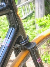
I have some nice bending bars and quickly got the BB in shape. Naturally, the bent lug ports needs some hammering to make sure that they conformed to the shape of the tubes. The lower head tube lug is a bit more difficult. It is somewhat like a bikini lug, in that there isn't much lug on the headtube, especially above the down tube. This means that its hard to clamp this part of the lug in place during the bending, and that this section doesn't have enough material to both fill the gap created by the bend and provide a good surface area on the head tube.  That's where this piece comes in. I traced the top of the lug onto a cutoff piece of head tube, and then cut it out.
This will get brazed into the corresponding section (see the second photo) of the lug, using brass filler. After some file work, it will fill the gap between the adjusted lug and the head tube. Some more filing on the outside of the lug will restore the outer shape (so that the shoreline of  the lug doesn't become twice as thick).
The actual joint will be brazed with silver filler, hence it won't heat up enough to weaken the brass filler used to modify the lug. Cool concept but plenty of work.
That's it for this post. Cheers,b
Its become clear to me that I shouldn't promise anything here - something always comes up to distract the dialog. So no promises, I think.
There many topics worthy of discussion, but what got me going tonight was this bit in Velo News
Now, I don't know about you, but I think big companies try to patent too much - especially broad concepts which they haven't invented or substantially developed. I think that Trek's 'Kamm Tail' fits this description. First of all, they are borrowing aerodynamic licks that have been employed repeatedly, for many years, and in a borad variety contexts - it's nothing new. And applying them to a bicycle isn't nothing new.
In fact, I've been experimenting with similar tubing shapes on TT bikes for over a year. And I didn't get the idea from Trek or anyone else in the bike business. In fact, I've long wondered why the so-called aerodynamicsts of the bike industry weren't exploring these ideas all along - thus making me wonder how many of them really know anything about aerodynamics.
It should be noted that an 8:1 aspect ratio is not optimal (as described in the article) for head-on air pressue. 8:1 represents a 12.5% ratio, which is near the maximum for the size of airfoil created by a bicycle tube, and the speeds at which a bike travels. Airfoils have scaling issues, and the smaller the airfoil is, the greater the challenges presented. If we want to talk about an optimal aspect ratio for dead-ahead air pressure, then we should be looking to something in the 8-10% range, meaning somewhere between 10:1 and 12:1. These are significantly different form an 8:1 ratio.
Of course, it's not just aspect ratio, but also the shape and size of the object which determines how slippery the object is. A really big object with a very slippery shape and aspect ratio may have more drag than a smaller object which has a sticky shape and aspect ratio. Or it may not. So much more needs to be pinned down, apart from the 8:1 ratio. But lets explore this further.
First, a round tube isn't much better than a square tube regarding the drag produced as an air stream hits it. Historically, metal aero-tubes had a round front and tapered rear. The rear fairing did little to improve aerodynamics over a normal round tube (although it never stopped a manufacturer from touting aero advantages). The simple learning here is that the leading edge (front) of the tube is the most critical shape for achieving low aero drag.
Trek suggests that the tube's profile should/can be cut off just past its broadest point. So let's look at this with their 8:1 profile and the UCI limit of 3:1 size.
Usually the thickest part of a wing is about 1/3 back from the leading edge. On an 8:1 ratio tube, with a 1" thickness, the chord (front to back distance) would be 8". If we took only the front 1/3 of that shape, the actual (as opposed to effective) chord would be reduced to 2-2/3". This creates a tube with a 1:2-2/3 aspect ratio. Which keeps us in the game vis a vis UCI rules. So far, so good.
Now lets talk about the Kamm Tail. The concept of the Kamm Tail (or more correctly Kamm Back) is that an aerodynamic automobile not only has too little aerodynamic downforce for stability, but actually can achieve aerodynamic lift as speed. The Kamm Back creates a low pressure area behind the vehicle (drag) which helps to maintain directional stability. So, while it works in conjunction with aerodynamic drag reduction, it actually is using drag to keep a car traveling in the correct direction. Which is quite different from what Trek is describing.
This doesn't make Trek's shapes or concept wrong, but shows how marketing mis-uses technology to explain and sell products.
OK, so let's get back to this shape thing. It looks like Trek has 1/3 of an inch left according to UCI rules. Should they max out the 3:1 ratio?
Aerodynamics occur in 3 dimensions. Any aerodynamicist who forgets this is unlikely to be successful for long. For example, a round down tube has a salami slice like shape (sort of an oval) as it presents itself to the wind - because the tube isn't vertical.
Moreover, the airflow will chase the lowest pressure areas. As with a swept wing on a jet, this means that on the downtube, there will be airflow from the further forward points (near the head tube) towards the bottom bracket - all else being equal. Perhaps you've seen an airplane with tiplets on the ends of the wing - they often look like small rudders. On the wing, air travels similarly down its length. Air below the wing has higher pressure than on top - so when the flow of air reaches the end of the wing, the high pressure below wants to flip over the top and fill the low-pressure area. This reduces lift and causes drag. The tiplet is designed to interfere with the spill of high pressure are from the bottom to the top, thus improving lift and reducing drag.
The sides of the downtube are symmetrical. So, if the wind is from dead-ahead, then there won't be a high and low pressure side. Nonetheless, all else being equal, the air flow along the downtube will be slightly downhill - which further elongates the oval presented to the wind.
It's possible that a tube that has a actual 3:1 ratio, presents itself to the wind at some other ratio - for example, instead of being 3" deep aerodynamically, it might be 4" long. Now this is of no particular advantage to one builder or another - they will all have a chance to leverage this phenomena. But it does prepare us for the next step.
Unlike what Trek says, the optimal cutoff for the airfoil is not at its widest point. The airflow needs to be stablized into a path similar to that it would take if the rear of the foil had not been truncated. The path from the thickes part of a wing to it's trailing edge is not a straight path. But it is generally the straightest part of the outline of the airfoil. Let's say that when we truncate an airfoil, we still need 10% of the overall chord length to be located behind the widest point of the airfoil. In reality, how much wing is required behind the maximum thickness is a function of the wing size, shape, and airspeed - so we're speaking in hypotheticals here when we use the numbe 10%.
Given that the base airfoil is 8:1 (per Trek), the 10% extra would be 0.8". Now, measured using the actual tube profile, we have a chord lenght of 2.667". Adding 0.8" to this gives us a chord of 3.467" - or an aspect ratio of almost 3.5:1 - well above the UCI limits. But let's think this over again. Assuming that we present a foil to the wind that is 4" deep and 1" wide, for a tube that has an actual 3:1 profile: In this case we have more of the aerodynamic airfoil with which to play. Let's move the widest point of the tube forward, so that it is 2.667" behind the leading edge when measured along the path of air flow. That means that we have 1.333" left behind the widest point, and this 1.333" is 13% of the original air foils chord. If we only needed 10% of the overall chord behind the widest point, then we have another 3% to play with.
Let me point out that the numbers above are not meant to emulate the reality of Trek's tube shape. Rather, they give the reader some insight into the sorts of opportunities and tradeoffs which exist in designing a an efficiently shaped downtube.
Now, if we have 3% of the chord left to play with, what should we do with this? If the wind always came from the front, we would probably just use it to truncate the shape closer to the trailing edge. However, the wind rarely is truely from directly ahead. All the points of the compass have equal likelyhood has being the source of any wind, and while the bike's ground movement adds another vector necessary to calculate effective (as opposed to true) wind direction, it should be obvious that we will commonly contend with a wind that is not from dead ahead. Further componding things this challenge is the fact that a bike rarely travels in a truely straight line. Instead bike and rider are constantly adjusting inputs, causing the front end to continually move back and forth.
So what? Think of our truncated airfoil. With wind dead ahead, a sharp corner at the rear has little impact. But, turn the wind direction 15 degrees to one side, and now this corner becomes a drag riser. We want to smooth the transition of the air flowing around this edge. A rounder shape will work better in these circumstances. So, the extra 3/10" in chord length might be best used to transition air around the rear of the tube, when its coming from a direction other than straight ahead.
With the widest part of the tube being located 2.667" from the leading edge, along the actual airflow, where is it located in a 90 degree cross section of the tube? Well, its 2.667/4.0 from the front. Solving the math gives us a maximum width 2" from the front of the tube. Similarly, the end of the rearward taper is located 2.600" inches back, leaving 0.4" that can be shaped to help cross winds get around the rear of the tube. All of this has been down in the context of UCI 3:1 rule.
Naturally, this isn't the end of the story. For example, cross winds see an assymetric shape, even though the tube is symmetric from left to right. This begs the question regarding whether there might be benefits to having a tube which is symmetric from front to back? Also, there are aerodynamic tools which can manange how well the airflow follows the contour of the airfoil. Remember when we (arbitrarily) suggested that the tube shape needed to include 10% of the overall (8") chord located behind the widest point of our tube? Flow managing tools could reduce this number without limiting our drag reduction. If so, then we would have more chord length available (within UCI rules) by which to manage how cross winds wrap around the down tube. And, what if there is another place where we can truncate the chord of the tube without compromizing aerodynamics? There is such a place, but that's a story for a different day.
Be aware, Trek is sloppy in describing what they are doing, greeding in suggesting that they may patent their technology, most likely accurate in describing what they doing as an improvement, and not producing an impact that you can measure within margins of error in real practice. Yeah, we haven't touched on this yet, but you the rider are the source aero drag. Yes the bike contributes, but its contribution is small. Your position on the bike; what accessories (water bottle(s), computer, tool bag, etc.) and how carry them; these are the important aspects of aerodynamics. Until you have these nailed, don't worry about the shape of your frame tubes, or how well hidden your brake may be.
Until next time, Cheers!
Rick
 That's where this piece comes in. I traced the top of the lug onto a cutoff piece of head tube, and then cut it out.
 the lug doesn't become twice as thick).