Saturday, March 12, 2011

A little progress

Well, it looks like at least another two weeks on the IV.  While I'm chomping on the bit, it's going to be a little while yet before I can start ramping up the shop again.

With that in mind, let me share a little project completed during all this medical who-ha.

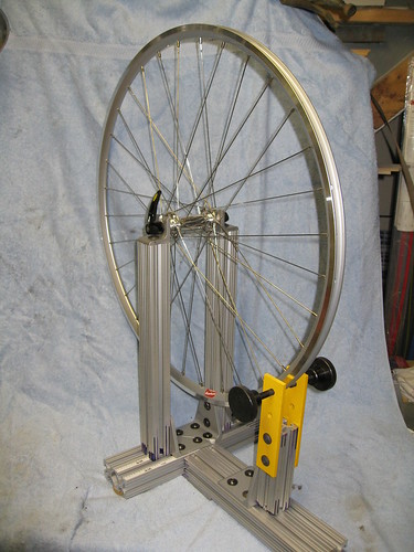
I've got a big, heavy, old Hozan truing stand.  It works, but its clumsy.  I've been thinking for some time about building its replacement.  Then my son asked for a truing stand for Christmas.- which further accelerated the process.

To me, a truing stand should be stiff, stable and well dampened.  It should be easy to adjust for a range of over lock-nut sizes and wheel diameters.  And, it should be easy to center the hub in the stand, so that centering the rim is not a separate process from building the wheel. A nice to have is the ability to mount a dial indicator for fine readings of true and round.

That's not a huge list of requirements, but buying a stand that meets them tends to be expensive.  For around $125, though, its possible to build such a stand using 80:20 extrusions as the foundation.

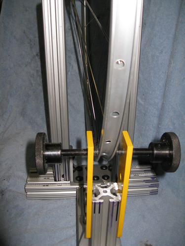
My son lives in CA, which added on further requirement: the stand has be able to be knocked down and shipped in a fixed-rate Priority Mail box.  As a consequence, on the stand I made, the cross frame is limited in size, so I had to come up with a way to mount the uprights so they would fit the cross piece and come together for a 100mm front OLD.

Note, the adjustment hand screws in the picture have brass heads and were prior to trimming to length.  These have been replaced with plastic headed hand screws, so they won't where out their threaded guide holes prematurely.  Also, not seen in the pictures are: connector plate between the two base pieces; three rubber furniture feet on which this stand sits.  These provide a tripod support (three points define a plane) which won't rock, and make sure that the stand doesn't slide around on the work surface.

Anyhow, I don't have any plans, per se, so I can't share them.  But all you really need to know is in the following pictures.  All parts not from 80:20 came from McMaster Carr, including the self-adhesive left and right hand metric scales used to align the uprights.


Monday, March 07, 2011

Been missing you guys.

Hey gang,

Sorry to be gone so long, but I've been busy with some medical issues.  Nothing I can't get past, just stuff that interferes with life for a while.  

It started in December with a herniated disk (symptom of age).  When that was cleared up, I developed a staph infection (no one can tell me how).  The staph was kinda ugly, but its now on the run.  I'm still running a portable IV of penicillin, but I go to the Dr. on Wednesday and expect to hear how much longer that will last.  Hopefully not to long cuz I can't really work in the shop with this thing.

Anyhow, as shop work gets up to speed, I'll be posting words/pix right here.

Cheers,

RG

Friday, February 18, 2011

A crucial time

Today I stand with the teachers, nurses, and all public employees of Wisconsin who are fighting for their rights. If you do too, change this to your status for the rest of the day.

You too can choose Freedom over Greedom, post this pledge to your blog or facebook page.

Monday, December 13, 2010

Techy Stuff

"In order to find the best compromise between performance and cost, the round tube may be sized such that its bending stiffness is identical to that of a square tube with the same wall thickness.  Using the first order findings of Eq. 2.12 and setting equal results in:  

wrd = cuberoot(16/3*Pi) * wsq 

Plugging the diameter wrd found in Eq. 2.18 into Eq 2.13, the torsional stiffness of a round tube can be found to be larger by a factor of 4/3 (33%) while being lighter by 7%."  

I may never become a commercial success at frame-building (or perhaps any pursuit) because of my resolute tendency to cry BS at anything that tickles me as marketing tekno-babble rather than real engineering.  And today, in any successful commercial endeavor, there there seems to be a lot of marketing tekno-babble.  No where is this more true today, than in the bicycle industry; where so much that is discussed, advertised, and written regarding design and bicycle attributes is just so much nonsense.  

Recently, I was perusing: Principles of Rapid Machine Design by Eberhard Bamberg, M.Sc., Advanced Manufacturing Systems Brunel University, 1993 Dipl.-Ing, Maschinenbau Universität Stuttgart, 1996  SUBMITTED TO THE DEPARTMENT OF MECHANICAL ENGINEERING IN PARTIAL FULFILLMENT OF THE DEGREE OF DOCTOR OF PHILOSOPHY at the MASSACHUSETTS INSTITUTE OF TECHNOLOGY, June 2000 © 2000 Massachusetts Institute of Technology All rights reserved.  This is the source of the opening quote.

Let's begin by acknowledging that my academic career stayed far away from the hard sciences and engineering, thus making my tastes in light reading that much more unusual.  And no, the goal of this read was not to learn anything about designing or building bicycles.  However, while I've known for quite some time that a round shape is the most efficient shape of tubing for resisting both bending and torsional forces; I haven't had a scholarly reference or mathematical formula to back up this understanding.  So, running across this quote, in the midst of a larger discussion of analyzing the properties of tubes, seemed like a bit of an early holiday present.

All of the large bike brands make much of the shapes of their tubes, suggesting that that they have found miraculous new ways to: 1) improve stiffness; 2) reduce weight; 3) improve ride qualities.  I'm calling BS right here, right now.  Stiffness is increased by increasing the diameter of tubes and/or increasing the wall thickness.  Weight is reduced by cutting down the amount of material in the tubes, either by using smaller diameter tubes, and/or decreased wall thickness.  Ride comfort, however, is a different question - and it is difficult to argue that tubing diameter or wall thickness is directly related to ride comfort.

Among stock phrases appearing in bicycle reviews, "... greater lateral stiffness combined with improved vertical compliance..." is probably the one most often ridiculed by the cognoscenti of bicycle design and building.  And this ridicule is truly well earned.  The side-view of a bike frame is essentially based on a Warren Truss, which is a very efficient structure for resisting the weight carried by a bridge.  In other words, it focuses on resisting vertical forces.

Viewed from the front, however, there is no structure to resist lateral forces except the form of the tubes themselves. 

Both the shape of a tube, and the form of a Warren Truss service to harness the opposing forces of tension and compression.  Both also gain stiffness by physically separating those opposing forces as far apart as possible (hence the greater stiffness of a larger diameter tube).  But the distances within tubes and between tubes vary by greater than an order of magnitude.  So while a round tube's inherent stiffness is equal in the vertical and horizontal planes, the Warren Turss does not offer this direction-independent equality of stiffness.

What does this mean?  A bicycle frame is more apt to bend laterally than vertically, regardless of what magazine writers or marketing specialists say. 

So maybe that's true, but how about a top tube that is flattened?  Surely its shape allows more vertical compliance and lateral stiffness than a round tube, because most of the material is oriented horizontally, right?  And this beneficially tunes ride characteristics?  Wrong Kemosabi!

Think of an I-beam: there is a vertical web connecting two horizontal plates.  Fundamentally, its the plates doing the hard work.  Why is this?  Well, the greater effective distance a portion of a beam is stretched or compressed, the more work that portion of the beam does in terms of preventing bending.  Get a compass, and draw three concentric circles.  The inner represents the bending of the lower plate of the I-beam, the middle circle represents the bending of the web, and the the outer circle represents the bending of the upper plate.  Clearly, the lower plate is compressed relative to the web and upper plate.  The upper plate is stretched relative to the web and lower plate.  And the web is merely bent.  Now this is a slight generalization of the forces are work, but it makes the point. 

A tube is more like a box beam, where there are two webs, one on each side, and two plates.  A beam is made more stiff by increasing the distance between the plates - thus increasing the differential between the compression and tension.  That squashed top tube causes the sides of the tube to be further apart from each other, and the top/bottom to be closer together.  So.... while it appears as if it should be stiffer laterally, and more flexible vertically, it is in fact the opposite. 

It's hard to beat round tubes for a bicycle frame.  Where there is a benefit to ovalizing them, it is generally to give a larger area with which to bond (using a weld/braze/glue/carbon wrap/or structural lug) to the adjoining tube - and not to tune the ride or stiffness.  And, that's the way it is.

Having beaten this point to death, my hope is that a few more folks will now recognize that: a) shaped tubing is just a marketing gimmick; b) frames flex laterally (or in torsion) rather than vertically.  And thereby they will be better informed consumers.

Cheers

Tuesday, November 09, 2010

Progetto Cycles

Progetto Cycles is now Smoked Out.  Interesting story, check it out.

Thursday, October 28, 2010

Vacuuming a Bike

OK, its been too long.  Its also hard to get good pictures in the middle of a very messy and time-sensitive process that requires at least both hands.  Whatever....

Here are some pix of the process:

I like to make my 'pre-pregs'  The CF and epoxy get wet out together in between layers of wax paper.  Key to this process is working the epoxy through the fabric, and pushing out as much air as possible.  Here is the last of the small reinforcements.


And here is a large reinforcement (made of a 4ply material)


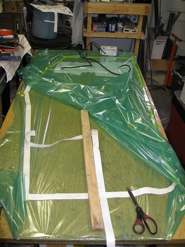
The bag starts with a piece of bagging film as long as my table and 2x as wide.  This is then eyeballed to determine where I'll lay down the sealing tape.


Sealing tape is laid down to form a perimeter, with the protective cover remaining on the backside.  The bag material is folded over this and the process of creating the bag begins.  Releasing a bit of the tape cover at a time, the material is sealed down on the tape.  The stick in the picture allows me to better control things inside the bag - sort of a third hand.  You can also see the breather felt at the end.  This will help transport air to the vacuum pumps, and soak up excess epoxy to keep it out of the pumps.  Part of the bag itself has been treated with a mold release to keep it from sticking to the epoxy.  Finally, you can see that there are two spigots attached to the bag and connected to the vacuum pumps.


The reinforcement is in place in the next picture.  Much effort has gone into smoothing it out while ensuring that it is in full contact with the underlying surface.  Also, there is a layer of perforated release material on top, held in place by some flash tape.  Unfortunately, the release material doesn't stretch like the bag, so it has various cuts and tucks and pieces, all with the intent of keeping it smooth with the CF, so we don't create many creases in the epoxy.


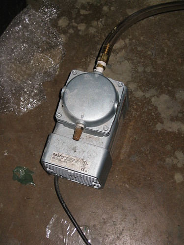
This now goes into the bag, which is sealed on its last side.  Then the pumps can go to work.  Here is the small one which pulls about 11 inches of mercury:


And here is the large one which pulls about 28 inches of mercury.


These are connected through a manifold so that neither, either, or both can run at any given time.

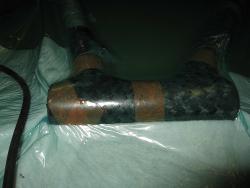
Once the vacuum starts things start to tighten right up.  Here we can see some issues with around the curves of the joints,  so I'll cut back the big pump and work the bag around here to smooth things out and make sure there is no air trapped.


And here is a frontal shot after resuming the vacuum:


Finally a shot of the rear triangle - you can see why I install a dummy axle during the bagging process.


Stick around, there are more pictures to come.

Townsend Cycles is officially Smoked Out

Check our Townsend Cycles at Smoked Out in the Velocipede Salon!

Saturday, October 16, 2010

Dornbox

OK, new builder thread is outed at Smoked Out: Dornbox Bicycles

If you're interested in custom bikes... Check him out!

Saturday, October 02, 2010

More on Carbon Fiber

Knowing that CF works best under tension, and in a straight line, it isn't a big step to accept that it doesn't liked to be 'crimped' into a woven fabric.  It's not that this can't be done, it's just that the zigzag nature of the path of the individual fibers doesn't fully leverage their strength.  This is not to say that a woven fabric of CF doesn't offer strength, just that it doesn't maximize the strength to weight ratio.

Similarly, a random felt of fibers usually have similar issues of crimping, as well as a large percentage of fibers that are bent, rather than straight.

This takes us back to uni-directional fibers as a usable, but not the only, way to wrap joints.  It's possible to wrap a thick thread of CF fibers (called tow) around and around the joint.  If properly impregnated with epoxy, and pulled very tightly, the resulting joint can effectively hold tubes together.  Implied in this is some thought to how much this nest of fiber must overlap each tube in the joint, and which directions are best for wrapping in order to control the vectors of force encountered by the joint.  In a tow wrapped joint, there is minimal crimping, and limited (as much as possible in a joint) bending of the fibers.  Probably the biggest difficulty is squeezing tightly enough to extract excess epoxy, and achieving a balanced spread of fiber around the joint.  There may be the temptation to sand to shape, but this risks breaking the fibers up into shorter segments which may be less strong due to less overlap between fibers that control sheer forces in the joint.

Sheer forces?  Think of a salami sandwich, with a stack of salami slices.  Try pulling a slice free - essentially the force between that slice and those adjacent is sheer.  Of course, most folks don't use wrapped tow joints, so we don't have to worry about this on bikes, right?  Wrong.

Individual layers of uni-directional fibers experience sheer stresses too!  And this can be the most destructive forces in the joints between tubes.  There are several ways to control sheer forces.  These include: having sufficient overlap between layers to ensure the joint's integrity; bonding all layers simultaneously so that there is a chemical bond between the epoxy of each of the layers; using some fibers/materials that pierce layers and act to tie them together.  All of these methods can and may be used in the manufacture of a CF bicycle frame.

If you've read this far, you're probably aware that CF is often available as pre-preg.  This means that the builder obtains CF with epoxy already impregnated in the fabric.  The epoxy has some degree of stability in its un-cured state (often maintained by refrigeration), and some means of causing it to cure (often through heat).

At a minimum, working with pre-preg requires the builder to have some form of refrigerator or freezer, and some kind of oven.  Naturally, this drives a significant investment, which requires some minimum level of sales to support same.  On the other hand, pre-pregs off some stability in handling compared to dry CF fabrics.  The epoxy in the pre-preg can hold the fibers in position while the material is wrapped around a joint.  With a dry CF, something (usually glue or a matrix of fine fibers) have to be bonded to one side to hold the CF fibers in alignment until wet epoxy is applied, and the fabric is wrapped around the joint.

Pre-preg is also a bit easier to layer up prior to curing.   For one thing, curing doesn't begin until heated, whereas wet epoxy starts the curing process as soon as its mixed up.  Depending on the blend, the builder has more or less time until the curing reaches a point where further handling is unproductive.

Also, wet epoxy acts a bit like lubricant between layers of CF.  And the layers of uni CF tend to be stiff and unwilling to bend around 3D shapes.  Trying to hold the layers in place, without wrinkling, while placing others on top, quickly becomes a six-handed puzzle.  If one hasn't strategized  the operation adequately, it can turn into a very frustrating experience, with epoxy and fiber ending up everywhere except where it needs to be.

I don't do the volume of work to justify the equipment necessary for pre-pregs.  But, fortunately there are a few fabric producers out there who have come up with some very workable solutions to these problems.  These are in the form of fabrics which have multiple layers of uni CF, oriented along different axises, which are held together by some loose stitching through the whole of the cloth, and occasionally very light layers of scrim bonded to the adjacent CF layers.  Even with the scrim, these fabrics drape easily over complex shapes. With a somewhat higher weight to strength ratio are knit fabrics which have lesser crimping than woven fabrics, while allowing for easy draping over three dimensions.

This is a picture of a knit tape applied to the backside of the head tube, top tube and down tube.  You can see how gracefully it follows the contours.


Prior to the main reinforcement of the joint, I use this knit fabric to establish basic strength of the join and help ensure that nothing about the vacuum bagging process changes alignment of the joint.  This tape is held in place during the cure with reversed electrical tape (sticky side out), which is stretched tightly around the joint.  The resulting pressure forces any excess epoxy out through holes that I punch in the tape.

From here I move to working with two specialty fabrics, made with fibers from Toray and Hexcel.  The first is a two-ply uni-CF with the plies aligned at +/- 45 degrees from the axis of the fiber.


Along the edge you can see the two plys.  This cloth has no scrim layer so only the loose white stitching holds it together.  You can see how easily the edge comes undone, and even how the individual bundles of CF are ready to quickly unravel.


The second one is a nine-ply uni-CF with the plies aligned 0, 90 & +/- 45 degrees.  You can see the not just the stitching on this, but also the scrim layer.  It's hard to see, much less count the 9 layers.


And where the scrim has been pulled away from the edge, you can see how quickly this fabric also unravels.


Along with these, I make selective use of traditional single-ply uni-CF tapes.  Between these fabrics, I can create layup schedules for each of the joints that have sufficient material (strength), and the proper directions of plys (to handle the vectors of force) to make great joints.  And because I am effectively working with fewer layers, of material more easily shaped to the joint, its possible to avoid the six-handed frustration of wet-wrapping joints.

Let's digress for a moment.  I have good sources for my materials, but I wouldn't call them robust.  My sources for state-of-the-art materials don't cater to small volume buyers, and the folks that do tend to do so as a favor.  So don't ask me where I buy my CF and I'll tell you no lies.  Also, don't ask me my specific lamination schedules.  I can't assure that your methods will be identical to mine, and I don't want any responsibility for the success of your joints.  Go get your own materials, practice, test, refine, repeat, until you have a working solution.  OK?  Great!

Fitting fabric to a joint is complicated.  I start with rough paper patterns.  Because paper doesn't adapt over 3D like my fabrics, these can only be rough.  But these give me a starting point, from which I can trim material until I have good coverage of a joint, including overlapping the material on itself (so that the tubes are wrapped through 360 degrees plus).  Then epoxy can be painted on the joint, and for thinner layers painted on the fabric, which is then applied to the joint.  Because multiple layers will be applied, I don't attempt to force the material to adhere to the tubing until the last layer is applied.  Special flashing tape helps to hold materials in position.  A release layer of some type is applied next.  Guess what: this stuff doesn't like to work in 3D.  Therefore there is cutting and fitting to make it conform to shape of the joint.  This too can benefit from flash tape.  Outside of this goes a layer of batting which serves as a conduit for the vacuum and acts to soak up any excess epoxy pulled out during the vacuum process.

We'll speak more about vacuum bagging at some future date, I'm sure.  But for now, this gives you an overview what I use, and how it goes together to make a CF bike frame.

So I'm done here for now (well, except for possible editting).  Hope you've found this informative.  Don't hesitate to ask questions.

Cheers,